


G RESET HOLE
Returns all settings to default value
and erases all memories
H °C/°F SWITCH
Selects between Centigrade (°C) and
Fahrenheit (°F) degrees
BEFORE YOU BEGIN
To ensure proper setup, please note the
following before you start:
• Assign different channels to different
remote units.
• Insert batteries in remote units before
doing so for the main unit (see
instructions for battery installation).
• Place the main unit as close as
possible to the remote unit
• Reset the main unit after installing
batteries. This will ensure easier
synchronization between the
transmission and reception of signals.
• Position the remote unit and main unit
within effective transmission range,
which, in usual circumstances, is
65 to 100 feet.
Refer to the REMOTE SENSOR
section for sensor setup instructions.
BATTERIES
The Thermo Hygrometer uses 2 UM-3
("AA") alkaline batteries.
1. Remove the screw to open the battery
door.
2. Insert the batteries strictly according
to the polarities.
3. Select the temperature display unit on
the °C /°F slide switch.
4. Replace the battery door and fasten
the screw.
5. Replace the batteries when the low-
battery indicator of the indoor
temperature lights up (Repeat the
steps described in "Before You Begin",
above)
shows when batteries are low for the
main unit or for the selected remote unit.
GETTING STARTED
Once batteries are placed in a given
remote sensor unit, it will start transmitting
information at 40-second intervals.
Also, for approximately a 3-minute
duration, the main unit will automatically
search for signals once batteries are
installed. Upon successful reception, the
individual channel temperature reading will
be displayed on the upper window and the
respective humidity reading on the lower
window. The main unit will automatically
update its readings at about 40-second
intervals.
If no signals are received, blanks "---" will
show and the RF signal indicator will not
show.
NOTE
SEARCH FOR A SENSOR SIGNAL
Press and hold IN / REMOTE for
2-seconds to enforce a 3-minute search.
This is useful in synchronizing the
transmission and reception of the remote
and main units. Repeat this step whenever
you find discrepancies between the
reading shown on the main unit and that
on the respective remote
unit.
DISPLAY TEMPERATURE / HUMIDITY
Display of readings from a remote sensor
or the main unit is a one-step procedure.
The remote sensor channel or the main
unit display is indicated under the readings.
INDOOR UNIT
Press IN/REMOTE until "in" is displayed
under the readings.
REMOTE SENSOR
Press CHANNEL until the appropriate
remote sensor channel is displayed under
the readings.
If no readings are received from one
particular channel for more than 15
minutes, blanks "---" will be displayed until
further readings are successfully
searched. Check the remote sensor to
ensure that t is secure and that the correct
channel has been selected. Optionally,
press and hold IN/REMOTE for 2-seconds
to enforce a search.
MAXIMUM / MINIMUM TEMPERATURE
/ HUMIDITY
The maximum and minimum recorded
temperature and humidity readings will
automatically be stored in the memory.
DISPLAY MAXIMUM / MINIMUM
MEMORY
1. Select the channel to be checked.
2. Press MEM / CLEAR once to display
the maximum reading and again to
display the minimum reading. The
respective indicators, MAX or MIN will
show.
CLEAR MEMORY
Press and hold MEM / CLEAR for
2-seconds. The current temperature and
humidity will be saved as the min / max
values until new records are set.
TEMPERATURE DISPLAY
Slide the °C/°F switch into the desired
position to select °C (Centigrade) or °F
(Fahrenheit) degrees display. The switch
is located on the bottom of the unit.
The switch on the main unit over-
rides any selection you may make for the
remote sensor (THGR238N).
NOTE
ZONE TEMP HUMIDITY
Any >70%
20 – 25 ° C
(68 - 77 ° F)
40 – 70%
<40%Any
This information is shown in the Humidity
Area when the current measurement is
displayed.
RF SIGNAL RECEPTION
The RF Signal Indicator shows the signal
receiving status for the main unit.
The unit is in
searching
mode.
Transmission
data are
securely
registered.
No signals.
SCAN FOR REMOTE SENSORS
To auto-scan between sensors, press and
hold CHANNEL for 2 seconds. Each
sensor's data will be displayed for
3 seconds. To end auto-scan, press any
button.
SEARCH FOR SENSOR
To search for a sensor, press IN /
REMOTE.
If the sensor is still not found,
check the batteries, obstructions, and
remote unit location.
Signals from household devices
such as doorbells, electronic garage doors,
and home security systems may cause
temporary reception failure. This is normal
and does not affect general product
performance. The reception will resume
once the interference ends.
Battery performance, and subsequently
the effective range, may be affected by
freezing temperatures.
SPECIFICATIONS
Dimensions 6.54 x 2.28 x 1.26
inches (L x W x H)
Weight 4.47 ounces
Operating range -5.0 to 50.0 °C
(23.0 to 122.0 °F)
Resolution 0.1 °C (0.2 °F)
Relative Humidity 25% to 95%
RF Frequency 433 MHz
Channel No. 1 - 3
Range 30 meters
(98 feet) with no
obstructions
Transmission every 40 seconds
Batteries 2 x UM-3 ("AA")
1.5 V alkaline
NOTE
NOTE
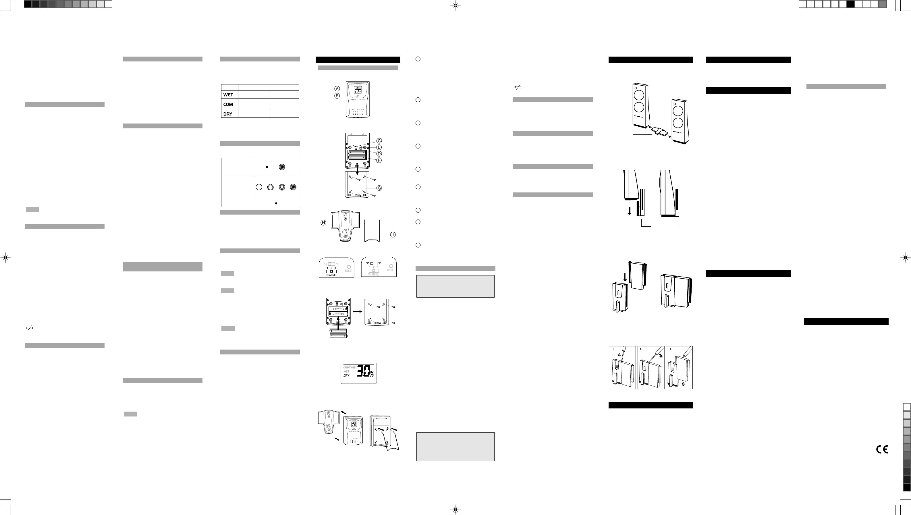
REMOTE SENSOR (THGR238N)
FEATURES
[ FIG D ]
[ FIG E ]
[ FIG C ]
[ FIG A ]
[ FIG B ]
ATwo-line LCD
Displays the current temperature and
humidity monitored by the remote unit
•Temperature display
• Humidity display
• Comfort-level indicator
B LED INDICATOR
Flashes when the remote unit transmits
a reading
C °C/°F SLIDE SWITCH
Selects between Centigrade (°C) and
Fahrenheit (°F)
D CHANNEL SLIDE SWITCH
Designates the remote unit Channel 1,
Channel 2 or Channel 3
E RESET BUTTON
Returns all settings to default values
FBATTERY COMPARTMENT
Accommodates two UM-3 or AA size
alkaline batteries
GBATTERY DOOR
HWALL-MOUNT HOLDER
Supports the remote unit in wall-
mounting
I REMOVABLE TABLE STAND
For standing the remote unit on a flat
surface
SETUP
Note: To ensure proper reception
between the main unit and the remote
sensor, follow these instructions
carefully.
1. Place both units as close as possible
to each other.
2. Remove the screws on the battery door
of the remote unit.
3. Assign a different channel to each
remote sensor by changing the channel
switch in the battery compartment of the
remote sensor. [FIG A]
4. Select the units of measurement for the
temperature display on the °C/°F slide
switch. [FIG B]
5. Install 2 alkaline batteries (UM-3 or "AA"
size 1.5V) strictly according to the
polarities shown. [FIG C]
6. Insert batteries or press the reset button
of the main unit. Follow the instructions
as set out in the User's manual.
7. Replace the battery compartment door
and secure its screws.
8. Position the remote sensor and main
unit within effective transmission range,
which in usual circumstances, is
30 meters.
Note: The effective range may be
limited by building materials and the
position of either the main unit or
remote sensors. Try various set-up
arrangements for best result.
Though the sensor is weatherproof, and
is meant for use outside, it should be
placed away from direct sunlight, rain, or
snow.
shows when batteries are low.
CHANGE CHANNEL
Once a channel is assigned to a unit, you
can only change it by removing the
batteries and repeating the above
procedure.
COMFORT LEVEL
The comfort level is based on the recorded
relative humidity. An indicator will be
displayed to show if the level is
comfortable, wet or dry. [FIG D]
TABLE OR WALL MOUNT
This sensor comes with a wall-mount
holder and a removable stand. Use either
to hold the unit in place. [FIG E]
SPECIFICATIONS
Remote thermo-hygro unit
Displayed
temperature range -50.0°C to +70.0°C
(-58.0°F to 158.0°F)
Proposed operating
range 0.0°C to +50.0°C
(32.0°F to 122.0°F)
Temperature
resolution 0.1°C (0.2°F)
Displayed relative
humidity range 2% RH to 97% RH
Humidity
Resolution 1%
Relative humidity
measurement
range 25% RH to 95% RH
RF Transmission
Frequency 433 MHz
Number of
channels 3
RF Transmission
Range Maximum 30 meters
Temperature
sensing cycle around 40 seconds
Power two (2) UM-3 or
“AA” 1.5V alkaline
batteries
Weight 80.5 gm (without
batteries)
Dimension 105 x 70 x 21 mm
(H x W x D)
TABLE OR WALL MOUNT
Your unit comes with a stand connector
for connecting it to other components.
Wall mount
bracket
Or, if there is already a wall mount bracket
installed, you can use a connector to align
the brackets.
Wall Mount
Bracket
Wall Mount
Connector
Un-install the brackets:
RESET SYSTEM
The RESET holes are located in the battery
compartments for each component. Press
with the point of a blunt object (such as a
paper clip) whenever the product is not
behaving as expected. This will return all
settings to default value.
SAFETY AND CARE
Wash the unit with a slightly damp cloth
and mild detergent. Avoid dropping the unit
or placing it in a high-traffic location.
WARNINGS
This product is designed to give you years
of service if handled properly. Observe the
following guidelines:
• Never immerse the unit in water. This
can cause electrical shock and damage
the unit.
• Do not subject the main unit to extreme
force, shock, or fluctuations in
temperature or humidity.
• Do not tamper with the internal
components. Doing so will terminate
the unit's warranty and may cause
damage. The unit contains no user-
serviceable parts.
• Do not mix new and old batteries or
batteries of different types.
• Do not use rechargeable batteries with
this product.
• Remove the batteries if storing this
product for a long period of time.
• Do not scratch the LCD display.
• Read this instruction manual thoroughly
before operating the unit.
The contents of this user manual and
technical specifications are subject to
change without further notice. Images
not drawn to scale. Do not make any
changes or modifications to this product.
Unauthorized changes may void your right
to use the product.
FCC STATEMENT
This equipment has been tested and found
to comply with the limits for a Class B
digital device, pursuant to Part 15 of the
FCC Rules. These limits are designed to
provide reasonable protection against
harmful interference in a residential
installation. This equipment generates,
uses, and can radiate radio frequency
energy and, if not installed and used in
accordance with the instructions, may
cause harmful interference to radio
communications.
However, there is no guarantee that
interference will not occur in a particular
installation. If this equipment does cause
harmful interference to radio or television
reception, which can be determined by
turning the equipment off and on, the user
is encouraged to try to correct the
interference by one or more of the following
measures:
• Reorient or relocate the receiving
antenna.
• Increase the separation between the
equipment and receiver.
• Connect the equipment into an outlet
on a circuit different from that to
which the receiver is connected.
• Consult the dealer of an experienced
radio/TV technician for help.
Warning: Changes or modifications not
expressly approved by Oregon Scientific
for compliance could void the warranty and
your authority to use this equipment.
DECLARATION OF CONFORMITY
The information below is not to be used as
contact for support or sales. Please call our
customer service number (listed on our
website at www.oregonscientific.com, or on
the warranty card for this product) for all
inquiries instead.
We
Name: Oregon Scientific, Inc.
Address: 19861 SW 95
th
Place,
Tualatin, Oregon
97062 USA
Telephone No.: 1-800-853-8883
Fax No.: 1-503-684-8883
declare that the product
Product No.: BHT663A
Product Name: Modular BTHR
Weather Station
Manufacturer: IDT Technology
Limited
Address: Block C, 9/F,
Kaiser Estate,
Phase 1,
41 Man Yue St.,
Hung Hom, Kowloon,
Hong Kong
is in conformity with Part 15 of the FCC
Rules. Operation is subject to the
following two conditions:
1) This device may not cause harmful
interference.
2) This device must accept any
interference received, including
interference that may cause
undesired operation.
ABOUT OREGON SCIENTIFIC
Visit our website (www.oregonscientific.com)
to learn more about other Oregon Scientific
products such as digital cameras, health and
fitness gear, and weather stations. The
website also includes contact information for
our customer service department, in case
you need to reach us.
COMFORT ZONE
The Comfort Zone indicates how
comfortable the climate is, based on
current temperature and humidity
measurements.
You can also mount it to a wall using a
wall mount bracket.
STAND
CONNECTOR
NOTE
P/N.: 086-003311-015
© 2004 Oregon Scientific. All rights reserved.
BHT663A lab test R1 1/9/04, 4:38 PM2
Black