


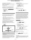


(4) Field curvature
An image plane of an object on a plane perpendicular to an
optical axis does not always become a plane perpendicular to
the optical axis, but it generally becomes a curved plane. This
symptom is called “field curvature.”
When field curvature is present, the image is more displaced as
it becomes closer to the periphery of the visual field. Therefore,
when the center of an image is brought into focus, blur occurs in
the peripheral areas of the image. To bring the entire image,
including the periphery, into clear focus, it is necessary to
adequately compensate for this type of aberration.
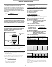
(5) Distortion
When there is no similar relation between a planar shape on an
object and a shape on the image plane, this is called “distortion.”
When distortion is present, a square image appears in a shape
of a barrel or pin-cushion as shown in Figure 9-6.
The microscope optical system contains some distortion. When
distortion is present, it can bring erroneous results of shape
measurements. When a microscope is used for precision
measurements, pay close attention to this aberration, for
example, by providing it with an aberration compensation
function.
(6) Chromatic aberration
Glasses used for optical systems have different refractive
indexes depending on the wavelength. This causes differences
in focal length between wavelengths and generates
displacement of image forming position. This phenomenon is
called “chromatic aberration,” which is sometimes subdivided
into axial displacement on the optical axis, called “axial
chromatic aberration” (or lateral chromatic aberration) and
displacement on the image plane, called “chromatic
aberration of magnitude.”
Many special glass materials are used, e.g., for apochromats
(MPlanApo in Olympus), to eliminate chromatic aberration in a
wide range from violet light (g-rays with wavelength of 435 nm)
to red light (c-rays with wavelength of 656 nm).
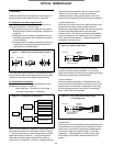
9.3 Wavefront Aberration
Since a long time ago, aberrations have been used in “geometric
optics,” which considers light as “light rays.” Microscope optical
systems are often used for observation of very small specimens
at a wavelength level, and sometimes adopt “wave optics,”
which regards light as “waves” and handles the phase
information, taking account of the influence of diffraction.
In such a case, “wavefront aberration” is used for evaluation.
As shown below, when requirements for ideal imaging are
satisfied in a microscope optical system, the spherical wavefront
(spherical waves) coming from a single point on an object
(specimen) is converted to plane waves through an ideal
objective lens. The plane waves are converted to spherical
waves through an ideal tube lens, and condensed to a single
point. The wavefront of these waves is called the “ideal
wavefront.”
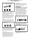
Based on the figure indicated for (1) spherical aberration, the
behavior of the wavefront in an optical system that has an
aberration is described below.
A difference (a degree of disagreement) between the ideal
wavefront and the actual wavefront shown above is called
“wavefront aberration.”
46
OPTICAL TERMINOLOGY
(a) (b) (c)
(a) (b) (c)
Figure 9-5 Astigmatism and Change in Spot
Shape in Different Focus Positions
(a) Barrel shape
type
(a) Pin-cushion
type
Figure 9-6 Distortion
Spherical
wave
Plane
wave
Spherical
wave
Plane
wave
Spherical
wave
Specimen Ideal
tube lens
Ideal
objective
lens
Image plane
Figure 9-7 Ideal Microscope Optical System
Objective lens with
spherical aberration
Figure 9-8 Illustration of Wavefront Aberration
Ideal
wavefront
Actual
wavefront
Specimen
Objective lens with
spherical aberration