


MOUNTING THE HOUSING
NOTE: This unit is designed for installation between 16" OC ceiling
joists with no framing necessary. if the building structure has 24" OC
joist construction, framing will be required.
1. Position housing between ceiling joists and adjust height to
finished ceiling. Loosen two (2) hex nuts for each mounting
bracket from inside the housing and make the adjustment. Tighten
the four (4) hex nuts.
NOTE: There are four (4) extra mounting slots in the housing long
sides for mounting or relocating the mounting brackets.
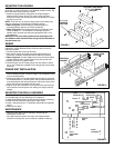
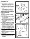
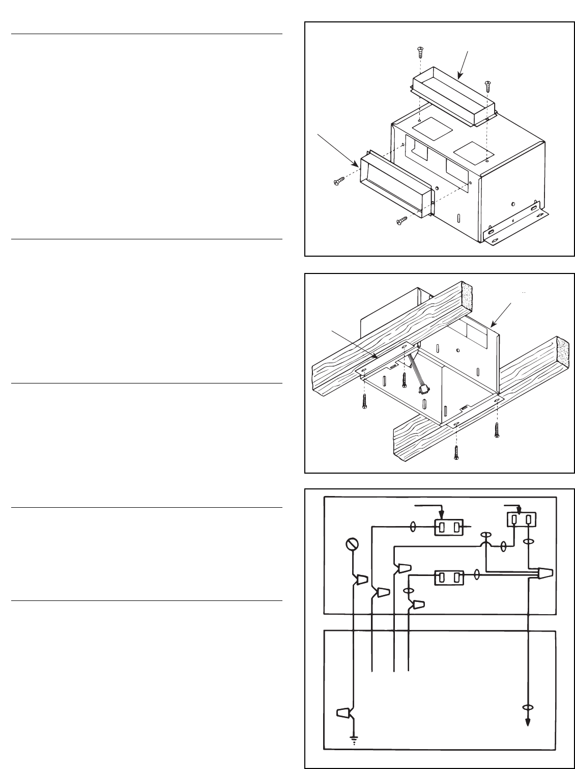
2. Refer to Figure 4. Screw housing to joists using holes in
mounting brackets and four (4) screws (furnished).
3. Refer to Figure 2 and mounting instructions included with caps.
Install standard 3
1
⁄4" x 10" ductwork from damper section to
outside wall or through roof and mount appropriate wall or roof
cap (optional).
IMPORTANT: Be sure nothing obstructs the discharge of the
unit. Make sure the insulation does not get into the ductwork or
into the blower unit.
WIRING
NOTE: All wiring connections must comply with local codes,
ordinances, and the National Electric Code and the unit must be
properly grounded.
1. Loosen screws and remove junction box.
2. Run 120vAC supply wiring with ground through switch box to
knockout in ventilator housing and secure with box connector.
3. Refer to Figure 5. Connect supply wires to the unit's wires. Black
to black; white to white. Connect ground to green ground lead.
4. Replace junction box; tighten screws.
5. Connect supply wire to a listed general use wall switch in switch
box or use a listed timer suitable for the voltage and current rating
of the fan.
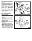
POWER UNIT INSTALLATION
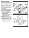
1. Refer to Figure 6. The Power Unit mounts with two hanger rods
to the mounting brackets. Insert the hanger rods through the holes
in the mounting bracket.
2. Position the power unit so that its discharge opening is in line with
the installed ductwork. Hold the power unit in position between the
mounting brackets and swing the hanger rods into the slots on the
power unit and securely tighten the wing nuts.
3. Plug the three-wire connector from the junction box into the three-
wire connector from the power unit, making sure plug is properly
aligned.
MOUNTING THE GRILLE ASSEMBLY
1. Place the reflector into the grille.
2. Insert light plug and night light plug into receptacles.
3. Using two provided screws, secure grille and reflector to housing.
4. Install 100 watt (maximum) light bulb into light socket.
5. Install 7 watt (maximum) C-7 candelabra type bulb into night light
socket.
6. Snap lens into place.
MAINTENANCE
• Disconnect the power before cleaning or performing any
maintenance on the unit.
• If the grille becomes soiled, use only a mild soap and water
solution for cleaning. Do not use solvents or abrasive cleaners.
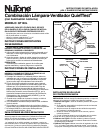
VERTICAL DISCHARGE
3
1
⁄4
" X 10" DAMPER
SECTION
FIGURE 3
3
1
⁄4" X 10"
DAMPER
SECTION
VENTILATOR
HOUSING
FIGURE 4
MOUNTING
BRACKET
LIGHT
RECEPTACLE
NIGHT LIGHT
RECEPTACLE
BLACK
WHITE
VENT
RECEPTACLE
BLACK
WHITE
BLACK
WHITE
WHITE
(COMMON)
SWITCH
BOX
FIELD
GROUNDING
WIRE
TO LIGHT SWITCH
TO NIGHT-
LIGHT SWITCH
TO FAN SWITCH
FIGURE 5