


VENTILATING AND WIRING
CUTOUTS
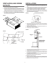
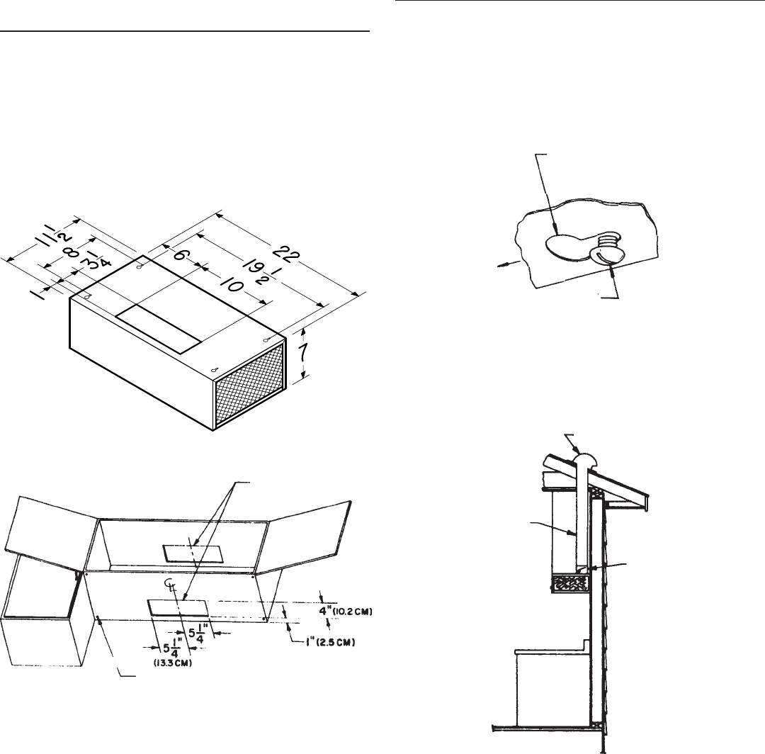
1. Mark locations on cabinet for ventilating duct and electrical wir-
ing from the dimensions given (FIGURE 1).
2. Cut holes at the marked locations to accommodate the venti-
lating duct and electrical wiring. Allow 3/4” extra on the ventilat-
ing opening toward the front of the cabinet. Be sure to minimize
openings, these will have to be sealed later (FIGURE 2).
3. Run house wiring through 1-1/2” diameter hole in cabinet or
wall. Be sure all wiring is in accordance with the National Elec-
trical Code and local ordinances.
2
INSTALLATION
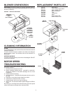
1. Remove blower housing and filters for easier installation. See
exhaust unit assembly illustration used for “Replacement Parts
List.”
2. Lift the exhaust unit into position and mark the hole locations
on the cabinet for each of the four keyhole mounting slots.
NOTE: REMOVE FASTENERS FROM PLASTIC BAG.
3. Remove the unit. Start all four screws (#10 x 5/8 slotted) in
center of the narrow neck of the keyhole slots previously marked
on the cabinet bottom (FIGURE 3).
4. There are predrilled holes on each side of the 3-1/2 x 10 hole in
exhaust unit for damper attachment. Use the small sheet metal
screws included (#8 x 1/4).
5. Remove junction box cover and appropriate knockout in ex-
haust unit for access to wiring.
6. Install proper ductwork (FIGURE 4).
7. Lift the exhaust unit into position simultaneously feeding house
wiring through exhaust unit knockout.
8. Tighten the four mounting screws to secure the exhaust unit to
the cabinet. Be sure the screw heads are in the narrow neck of
the keyhole slots (FIGURE 3).
9. Complete electrical wiring in junction box according to the Na-
tional Electrical Code and local ordinances.
10. Replace junction box cover.
11. Seal holes around ventilating pipe and wiring passing through
ceiling or walls with caulking or insulation to prevent heat loss.
12. Replace blower housing and filters.
DAMPER
RAIN CAP
3-1/4” x 10”
DUCT
IF RAIN CAP HAS A
DAMPER, REMOVE
DAMPER BLADE
KEYHOLE SLOT IN CANOPY
SCREW
(IN INSTALLATION PARTS BAG)
CABINET CUTOUTS
STARTER HOLES
FIGURE 1
FIGURE 2
FIGURE 3
FIGURE 4