


WIRING CONNECTIONS
All wiring must comply with local codes and unit must
be properly grounded.
1. While making wiring connections, support the heater
assembly on the bottom of the rough-in frame.
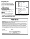
2. For 120 Volt operation, make wiring connections as shown
in Figure 4.
3. For 240 Volt operation, make wiring connections as shown
in Figure 5.
4. Use wire nuts to make connections. Insulate all
connections with electrical tape.
SECURING THE HEATER
1. Dress all wiring back to into junction box.
2. Locate center holes in housing flange and align with
mounting holes in grille.
3. Use two provided screws to attach grille to housing.
OPERATION
Turn thermostat fully clockwise to HIGH position. Allow
heater to run until room is at desired temperature. Adjust
thermostat as required to maintain desired temperature. Turn
the thermostat to FULL COUNTERCLOCKWISE position when operation is no longer desired.
Thermal protector: If for any reason temperatures increase beyond normal limits, a safety thermal fuse will shut heater off. The
heater will require servicing by a qualified electrician.
Check entire installation to determine cause of overheating.
4
1
2
3
4
1
2
3
FIGURE 4
FIGURE 5
120vAC
240vAC
GREEN OR BARE
GROUND
GREEN
GROUND
WHITE
BLACK
BLACK
RED
WHITE
YELLOW
120vAC
60HZ
GREEN OR BARE
GROUND
GREEN
GROUND
RED OR WHITE
BLACK
BLACK
RED
WHITE
YELLOW
240vAC
60HZ
NO
CONNECTION
NO
CONNECTION
Product specifications subject to change without notice.
4820 Red Bank Road, Cincinnati, Ohio 45227
Printed in U.S.A., Rev. 2/2005, Part No. 44960