


Product specifications subject to change without notice.
4820 Red Bank Road, Cincinnati, Ohio 45227
Printed in U.S.A., Rev. 11/01, Part No. 34114
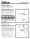
FIGURE 3
Existing Construction
1. Choose heater location. make sure the heater will not be
mounted closer than 6" from a vertical surface or 5" from
the floor.
2. Refer to Figure 2. Make wall cutout next to a wall stud.
Cutout size: 8
1
⁄8" high x 11" wide.
NOTE: Cutout must be 4
5
⁄8" above inside of wall.
3. Refer to Figure 3. Remove thermostat mounting bracket
and disconnect wiring terminal from the thermostat to
heater unit. Remove the four (4) screws securing the unit
to the housing. Run wiring from circuit breaker or fuse box
to wall switch (not provided) then to heater location.
4. Install box connector into wiring entrance hole in housing's
junction box.
5. Pull wiring through cutout and secure cable to box
connector. Allow 6" of wiring to make connections.
6. Insert bottom of housing into cutout first. Push unit down
into position.
7. Re-install the mounting guides and secure to wall as
illustrated in Figure 3. IMPORTANT: The wall surface will
fit between the mounting guide bracket and the plaster
flange. The housing's flange must be flush with the
finished plaster line.
WIRING CONNECTIONS
All wiring must be in compliance with local and national
electrical codes.
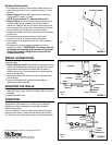
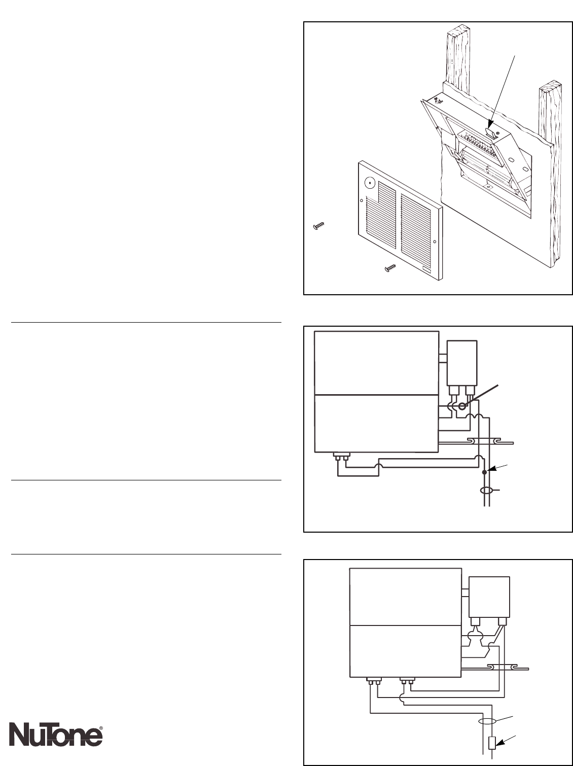
1. Refer to Figures 4 and 5. Reconnect thermostat wire from
heater unit. make wiring connections in junction box: black
supply wire to black lead from thermostat and white to
white or red to red. Connect ground wire to green ground
screw in junction box.
2. Make connections with listed wire nuts and insulate with
electrical tape.
3. Dress all wiring back into junction box and replace
thermostat mounting bracket.
MOUNTING THE GRILLE
1. Locate center holes in housing flange and align with
mounting holes in grille. Secure to housing with two screws
provided.
2. Install thermostat knob.
OPERATION
Turn wall switch on and turn thermostat fully clockwise to
high position. Allow heater to run until room is at desired
temperature. Adjust thermostat as required to maintain
desired temperature.
Thermal protector: If for any reason temperatures increase
beyond normal limits, a safety thermal fuse will shut heater
off. The heater will require servicing by a qualified electrician.
MOUNTING GUIDE
FIGURE 4
BLOWER
HEATER
BLACK
WHITE
YELLOW
MOTOR
NOTE:
Disconnect
black wire
to change
wattage of
unit to
750 watts
THERMOSTAT
STRAIN
RELIEF
YELLOW
BLACK
BLACK
WHITE
FUSE
120 volt
unit
FIGURE 5
BLOWER
MOTOR
THERMOSTAT
STRAIN
RELIEF
YEL.
YELLOW
BLACK
BLACK
BLACK
RED
RED
FUSE FUSE
240 volt
unit