3
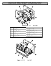
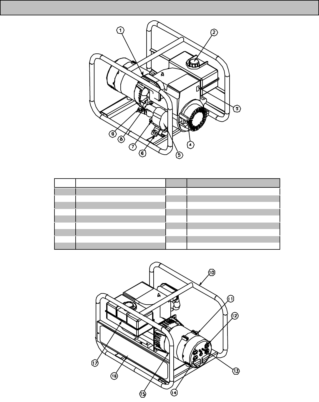
MACHINE COM PONENT IDENTIFICATION
Figure 1 (Ref. 1-9) fig.01858
Ref. Description Ref. Description
1 Muffler 10 Protective Frame
2Gas Cap 11 Grounding Screw
3 Engine Stop Swi tch 12 120V 20A Duplex Rec
4 Recoil 13 Circuit Breakers
5 Air Cleaner 14 240V 20A Duplex Rec.
6 Vibration Isolation Mount 15 Generator Head
7 Oil Drain Plug 16 Warning Instructions
8 Choke Lever 17 Gas Tank
9 Dipstick
Figure 2 (10-17) Fig01857


