HY70OM-8/99
10
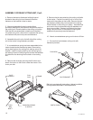
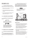
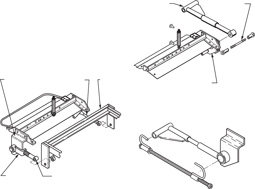
4. Remove the two top fasteners holding the pivot
bracket to the cutting unit and loosen the bottom
fastener so the bracket is free to rotate.
5. Align and assemble the spring and pull arm
previously attached to the tractor to the pull arm shaft on
the cutting unit. Place the belt on the cutting unit pulley.
With the pull arm assembled, rotate the pivot bracket
into place using it as a lever arm to compress the spring
and reattach with previously removed fasteners.
6. Assemble the pull rod on the left side of the cutting
unit to the tractor using fasteners provided.
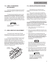
7. A counterbalance spring has been assembled to the
tractor located under the steering tower. Remove the
spring bushing from the cutting unit making note of its
location. Insert the spring bushing into the spring loop,
pull directly down on the spring and reinsert the fastener
provided thru the bushing into the hole on the cutting
unit.
8. Remove the tie wraps securing the lift chains and
attach the chains to the lift arm under the tractor. One
chain per side.
ASSEMBLY OF REAR CUTTING UNIT, Con't.
PIVOT
BRACKET
PULL
ROD
FRAME
PUSH ARM, SPRING
& SLEEVE
PUSH
ARM
SHAFT
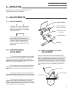
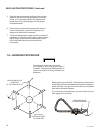
9. Remove the tie wrap attaching the cutting unit belts
to the tractor. Position the cutting unit in front of the
tractor with the pulleys to the inside. Remove the two
top fasteners holding the pivot bracket to the cutting.
Place the belt on the cutting unit pulley. Assemble the
push arm to the pivot bracket using the washers and
snap ring provided. Rotate pivot bracket into place
using it as a lever arm to compress the spring and
reattach with previously remove fasteners.
10. Attach counterbalance spring and chains to lift bar.
11. Connect link bar between cutting units with
fasteners provided.
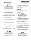
Belt tool, complete with instructions, (below) available
through National Mowers Parts Department.
LINK BAR
PUSH ARM
PIVOT BRACKET
PART # 070008


