


GB
13
F-030771L
WARNING: Always keep the nut (3)
tight that holds the blade (1). A
loose nut or blade can cause an
accident.
9. Tighten the nut (3) that holds the blade (1) to
a torque of 30 foot pounds (41,5 Nm).
10.Install the mower housing. See “How To Re-
move The Mower Housing”.
How To Adjust The Blade Rotation
Control
WARNING: To prevent an injury, the
blade rotation control must operate
correctly.
In normal usage, the blade rotation control will
not require an adjustment. However, if the cut-
ting performance decreases or the quality of cut
is poor, make the following changes.
1. When you mow, make sure the throttle con-
trol in in the FAST position.
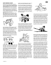
2. (Figure 8) Move the blade rotation control to
the DISENGAGE position (1).
3. Stop the engine. Disconnect the wire from
the spark plug.
4. Check the blade(s). Keep a sharp edge on
the blade(s). A blade that is not sharp will
cause the tips of the grass to become brown.
5. (Figure 9) Disconnect the blade drive
spring (2) from the blade control rod (1).
Move the blade drive spring (2) to the
middle hole (4). This will increase the tension
on the mower drive belt.
6. Attach the wire to the spark plug. Mow for a
short distance and again check the quality of
cut. If necessary, move the blade drive
spring (2) to the bottom hole (5)
7. Again check the quality of cut. If the quality of
cut has not improved, replace the mower
drive belt. See “How To Replace The Mower
Drive Belt”. If the replacing the belt does not
correct the problem, take the unit to an auth-
orized service centre.
8. Move the blade rotation control to the DIS-
ENGAGE position. Stop the engine.
9. (Figure 10) Check the operation of the blade
brake. Rotate the pulleys with your hand.
Make sure the brake pads (7) are pressed
tightly against the pulleys
WARNING: If the brake pads (7) do
not press tightly against the
pulleys, take the unit to an author-
ized service centre.
10.(Figure 8) Move the blade rotation control to
the ENGAGE position (2).
11. (Figure 10) Check the pads for the blade
brake (7). If the pads are excessively worn
or damaged, replace the brake pad assem-
blies. Correct replacement parts and assist-
ance are available from an authorized
service centre.
12.Attach the wire to the spark plug. Mow for a
short distance and again check the operation
of the blade rotation control.
13.When you move the blade rotation control to
the DISENGAGE position, all movement will
stop within five seconds. If there is move-
ment of the belt or the blades continue to ro-
tate, engage and disengage the blade
rotation control five times to remove any ex-
cess rubber from a new mower drive belt. If
you need assistance, take the unit to an
authorized service centre.
14.(Figure 9) If you replace the mower drive
belt, move the blade drive spring (2) to the
top hole (3).
How To Adjust The Shift Lever
(Figure 18)
If the NEUTRAL position on the shift lever does
not match neutral on the gearbox, adjust the
shift lever as follows.
1. Stop the engine.
2. Disconnect the adjuster nut (2) from the
shifter bracket (3).
3. Make sure the shift lever is in the NEUTRAL
position.
4. Push the unit forward. Make sure the gear-
box is in neutral.
5. To align the adjuster nut (2) with the hole in
the shifter bracket (3), turn the adjuster nut
(2).
6. Connect the adjuster nut (2) to the shifter
bracket (3).
7. Make sure the NEUTRAL position on the
shift lever matches neutral on the gearbox.
How To Check And Adjust The Clutch
(Figure 11)
If the motion drive belt is loose, the clutch will
slip when; going up a hill, pulling a heavy load,
or the unit will not move forward. Adjust the
clutch as follows.
WARNING: Before you make an in-
spection, adjustment, or repair to
the unit, disconnect the wire to the
spark plug. Remove the wire from the
spark plug to prevent the engine from
starting by accident.
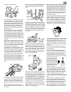
1. Check the routing of the motion drive belt.
Make sure the belt is installed correctly and
is inside all the belt guides.
2. Remove the cotter pin (1), washer (2), and
brake spring (3) from the adjustable nut
(4).
3. Disconnect the adjustable nut (4) from the
brake lever assembly (5) and the parking
brake latch (6).
4. Align the hole in the brake lever (5) with the
hole in the frame. Hold the brake lever (5) in
place with a 6 mm pin or bolt (7).
5. Pull the clutch rod forward until tight. Turn the
adjustable nut (4) until the nut will fit through
the hole in the brake lever (5).
6. Assemble the adjustable nut (4) to the
parking brake latch (6), brake lever (5) and
brake spring (3). Fasten with the washer (2)
and cotter pin (1).
7. Remove the 6 mm pin or bolt (7).
8. If the belt still slips after the clutch has been
adjusted, then the motion drive belt is worn
or damaged and must be replaced. See
“How To Replace The Motion Drive Belt”.
How To Check And Adjust The Drive
Brake (Figure 12)
Completely push the clutch/brake pedal forward.
Set the parking brake. Move the shift lever to the
neutral (N) position. Push the unit. If the rear
wheels rotate, adjust or replace the brake pads.
Adjust the drive brake (1) as follows.
1. The location of the drive brake (1) is on the
right side of the gearbox (3).
2. Make sure the parking brake is set and the
shift lever is in neutral (N). Turn the hex nut
(2) in a clockwise direction until the rear
wheels do not turn when the unit is pushed
forward.
3. Release the parking brake and push the unit.
If the unit does not roll, turn the hex nut (2)
in a counter-clockwise direction until the unit
rolls.
4. Set the parking brake. Push the unit. If the
rear wheels do not turn, the drive brake (1)
is correctly adjusted. Release the parking
brake.
WARNING: If you cannot correctly
adjust the drive brake, replace the
brake pads. Correct replacement
parts and assistance are available from an
authorized service centre.
How To Remove The Battery (Figure 4)
To charge or clean the battery (1), remove the
battery (1) from the unit as follows.
WARNING: To prevent sparks, dis-
connect the black battery cable (8)
from the negative (-) terminal be-
fore you disconnect the red cable (5).
WARNING: The battery contains
sulphuric acid which is harmful to
the skin, eyes and clothing. If the
acid gets on the body or clothing, wash
with water.
1. Disconnect the black cable (8) from the
negative (-) terminal.
2. Disconnect the red cable (5) from the posi-
tive (+) terminal (4).
3. Lift the battery tray (3) and the battery (1)
out of the unit.
How To Charge The Battery (Figure 4)
WARNING: When you charge the
battery, do not smoke. Keep the
battery away from any sparks. The
fumes from the battery acid can cause an
explosion.
1. Before you charge the battery (1), remove
the battery (1).
2. To charge the battery (1), use a 12 volt bat-
tery charger. Charge at a rate of 6 amperes
for 1 hour.
3. Install the battery (1).
WARNING: To prevent sparks,
fasten the red cable to the positive
(+) terminal before you connect the
black cable.
4. Fasten the red cable (5) to the positive (+)
terminal (4) with the fasteners as shown.
5. Fasten the black cable (8) to the negative
(-) terminal with the fasteners as shown.
How To Level The Mower Housing
(Figure 13 and Figure 14)
If the mower housing is level, the blade will cut
easier and the lawn will look better.