


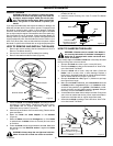
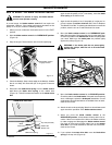
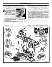
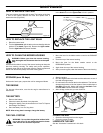
WARNING: The lift lever
is spring loaded. Make
sure the lift lever is locked
in the LEVEL ADJUST-
MENT position.
Level Adjustment
Position Figure 21
MAINTENANCE
26
F–030745L
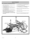
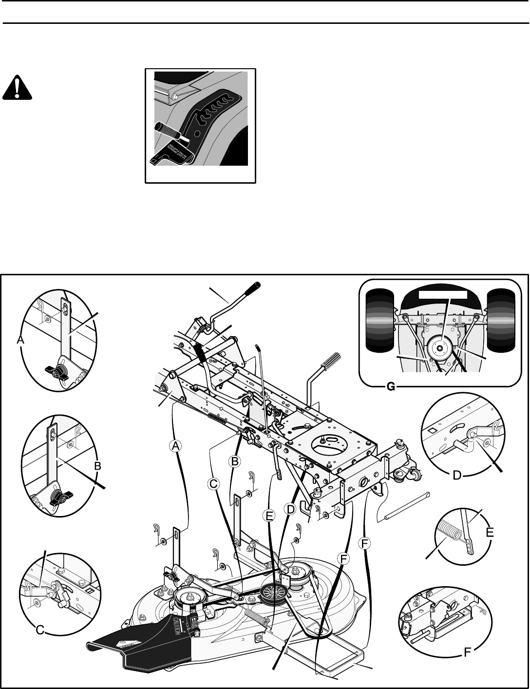
HOW TO REMOVE THE MOWER HOUSING
1. Move the blade rotation control to the DISENGAGE position.
2. Move the lift lever to the level adjustment position (Figure 21).
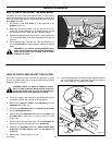
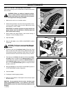
3. Remove the hair pins and the
washers from the adjuster
arms (Figure 22). See illustra-
tions “C” and “D”.
4. Remove the hair pins and wash-
ers from the suspension links.
See illustrations “A” and “B”.
5. Disconnect the extension spring from the blade control rod.
See illustration “E”.
6. Disconnect the front hanger from the axle support. See
illustration “F”.
7. Remove the mower drive belt from the stack pulley.
8. Pull the mower housing away from the right side of the unit.
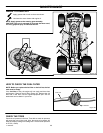
9. To operate without the mower housing, move the lift lever to the
TOP position.
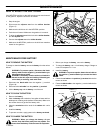
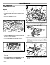
HOW TO INSTALL THE MOWER HOUSING
1. Push the mower housing under the right side of the unit.
2. Put the mower drive belt around the stack pulley. Make sure
the “V” side of the mower drive belt is against the stack pulley.
Also, make sure the mower drive belt is not twisted.
3. Attach the front hanger to the axle support with the hanger
rod. Fasten with the fasteners as shown. See illustration “F”.
4. Make sure the mower drive belt is between the stack pulley
and the two belt guides. See illustration “G”.
5. Attach the suspension links to the lifter assembly. Fasten
with the washers and hair pins. See illustrations “A” and “B”.
6. Attach the right and the left adjuster arms to the suspension
brackets. Fasten with the washers and hair pins. See illustra-
tions “C” and “D”.
7. Attach the extension spring to the blade control rod. See
illustration “E”.
8. Move the blade rotation control to the ENGAGE position.
Make sure the mower drive belt is inside all the belt guides.
9. Make sure the mower housing is level. See the instructions on
“How To Level The Mower Housing”.
10. Check the operation of the blade rotation control. See the in-
structions on “How To Adjust The Blade Rotation Control”.
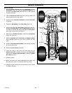
Lifter
Assembly
Blade Rotation
Control
Hanger Rod
Mower Drive Belt
Lift Lever
Figure 22
Front Hanger
Extension
Spring
Blade
Control Rod
Suspension
Link
Adjuster
Arm
Adjuster Arm
Belt
Guide
Belt
Guide
Stack Pulley
Mower Drive Belt
Suspension
Link