25
MAINTENANCE
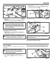
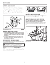
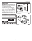
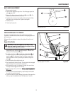
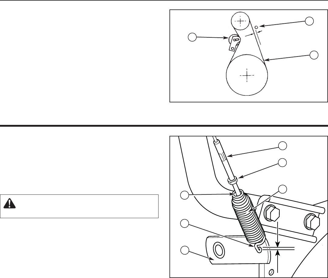
Adjusting Belt Drive Figure 28
BELT GUIDE ADJUSTMENT
1. Remove spark plug wire.
2. Have someone engage the auger drive. This will engage auger idler
pulley (A
A
, Figure 28).
3. Measure the distance between the belt guide (B
B
) and belt (C
C
). The
distance should be about 1/8 inch (3 mm).
4. If adjustment is necessary, loosen belt guide mounting bolt. Move
belt guide to the correct position. Tighten mounting bolt.
5. Install belt cover.
6. Connect spark plug wire.
1/8” (3mm)
Screw
CHECK AND ADJUST THE CABLES
The cables are adjusted at the factory and no adjustment should be
necessary. If the cables have become stretched or are sagging adjustment
will be necessary.
Whenever belts are adjusted or replaced, the cables will need to be ad-
justed.
Auger Drive Cable
WARNING: Do not over-tighten, as this may lift the
lever and cause the auger drive to be engaged without
depressing the auger drive control.
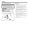
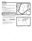
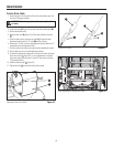
1. With the auger drive control lever released, the hook (A
A
, Figure 29)
should barely touch the lever (B
B
) without raising it. There can be a
maximum of 1/32" (0.8 mm) clearance.
2. To adjust, loosen the nut (C
C
) by holding the adjusting flats (D
D
) and
turning the nut. Then, turn the adjusting flats and hold the adjust-
ment screw (E
E
). The adjustment screw is a phillips screw and the
head can be held or turned by inserting a screwdriver through the
spring (F
F
).
3. Hold the adjusting flats and tighten the nut.
4. Start the engine and check the auger. The auger must not be engaged
unless the auger drive control lever is depressed.
5. With the engine running, fully depress the auger drive control lever.
The auger should engage and run normally.
6. Release the auger drive control lever. T
The auger must stop within five
(5) seconds.
7. If the auger does not operate properly, stop the engine and recheck
the auger drive cable adjustment.
8. If the drive linkage is properly adjusted, the tension of the auger drive
belt may require an adjustment (see “Belt Adjustment” section).
1/32”
(0.8mm)
Adjusting Auger Drive Cable Figure 29
A
A
B
C
D
E
F
B
C


