


Control Outputs
The following are provided:-
• Switched +ve RUN relay and START outputs, used for
controlling the engine fuel and starter motor circuits.
• A –ve DC (open collector transistor), common ALARM
output, used for remotely signalling a fault condition.
Fault protection and Alarm System
After the operator has started the engine and the fault
override timer has expired, the Keystart monitors for engine
and plant faults through remotely connected switch sensors.
Dedicated inputs are provided for Low Oil Pressure and
High Engine Temperature switch sensors. 1 or 2 additional
inputs may be used for general purpose ‘plant fail’ contacts.
Switches at the rear allow the inputs to be configured for
use with remote contacts which either open or close during
fault, with wiring polarity to either +ve or –ve DC.
The Keystart may optionally be fitted with an engine
overspeed trip, available in alternator sensing (generator
AC, 50/60Hz) or magnetic pickup sensing variants.
If any of the above faults occur, Keystart will:-
• turn off its RUN output (stopping the engine)
• indicate the fault on the appropriate front facia LED
• activate its Alarm output (to remotely signal that a
fault has occurred).
The automatic fault shutdowns operate on a first-up and
latching basis - subsequent faults are not indicated and the
displayed fault can only be cleared by switching the
Keystart to STOP.
Charge Fail Warning
A charge failure warning LED is provided for use with an
engine driven charge alternator. The charge alternator’s
WL terminal is connected to the Keystart, which will in turn
monitor the WL voltage and provide the alternator with
excitation current at engine start up.
Installation
The Keystart uses a DIN standard 96 x 96 mm casing,
designed for mounting in a control panel cut-out (92 x 92mm
DIN). Electrical connection is through a pair of ‘two-part’
type terminal blocks at the rear of the unit, with 2 separate
¼” blade terminals on overspeed versions for the
tachometer or calibration meter.
Also at the rear is are 4 switches for the setting of the
supply voltage and alarm input configurations, and up to 3
potentiometers: one to set the fault ‘override’ time (all units),
and 2 more to set the speed calibration and overspeed trip
level, where fitted.
When ordering, please specify:–
a) Base unit type:-
Keystart 9700: no overspeed
Keystart 9701: magnetic pickup sensing overspeed
Keystart 9702: AC alternator (50/60Hz) overspeed
b) Options:-
‘A’: auxiliary control/preheat option
N.B: stock units are supplied with switch settings for 24VDC
power supply, inputs closing to –ve DC during fault.
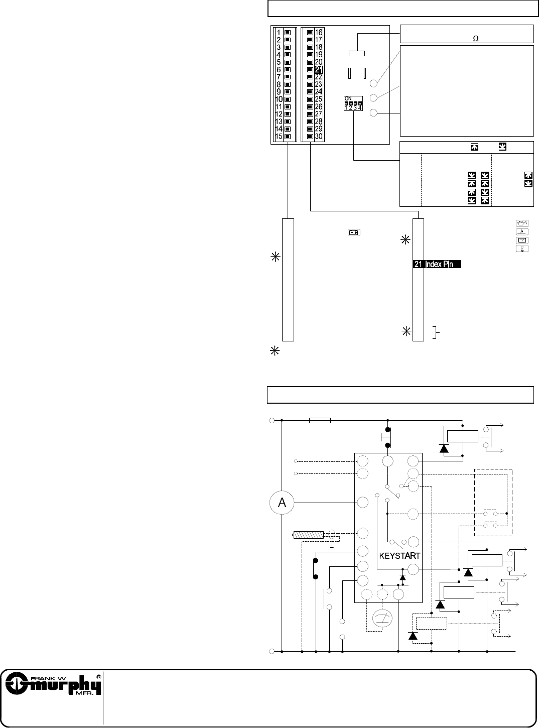
Typical Connection Circuit
RPM/Calib.
Meter
L
N
– VE DC
+ VE DC
30
29
Start
Emergency
Stop
RUN
Run
Stop
Run
Remote
Start
(’A’ option only)
Start
+
22
23
4
1
–
fuel
alarm
starter
preheat
(’A’ option
only)
15
63
Plant Fail
HET
LOP
19
2
16
17
5
–
+
WL
RPH
RAL
Aux
RST
RFL
Generator AC
(KEY9702 only)
Magnetic pickup
(KEY9701 only)
15
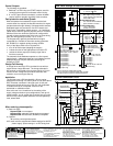
Rear Facia Settings & Electrical Connection
– ve DC power supply
Charge fail input
+ve DC power supply
Aux. input ('A' option)
Mag. pickup input (KEY9701 only)
Alarm output: –ve DC, < 250mA
Aux./preheat output: +ve DC
('A' option only)
- No connection -
- No connection -
- No connection -
- No connection -
- No connection -
- No connection -
- No connection -
- No connection -
Note:–
Pin 5 is not used on models 9700 and 9702.
Pin 18 is not used on overspeed models 9701 and 9702.
Pins 29 and 30 are not used on models 9700 and 9701.
- No connection -
- No connection -
- No connection -
- No connection -
- No connection -
- No connection -
1
2
3
4
5
6
7
8
9
10
11
12
13
14
15
16
17
18
19
20
22
23
24
25
26
27
28
29
30
S1
Not
Used
Switch Settings(N.B. = up = down)
Fault Inputs:–
closed –ve
closed +ve
open –ve
open +ve
Supply:–
12 V DC
24 V DC
S2 S3
S4
VR3: Fault override timer:–
< 10 to > 30 seconds
clockwise to increase
100 - 130% of nominal calibrated
speed, clockwise to increase
VR2: Overspeed trip level:–
With engine running at normal
speed, adjust VR1 until calibration
meter reads 0.75mA.
VR1: Nominal speed calibration:–
Tachometer/calibration output:–
0 – 1mA into 75 meter
VR1
+ve
–ve
VR2
VR3
Input 1: Low Oil Pressure
Input 2: High Engine Temp.
Input 3: Plant Fail (9700 only)
Input 4: Plant Fail
Fuel output: + ve DC, 16A max.
Start output: + ve DC, 15A max.
Generator AC: 90 - 300 VAC
(KEY9702 only)
L
N
Since 1939
Frank W. Murphy Manufacturer
PO Box 470248, Tulsa, Oklahoma 74147, USA
Tel: + 1 918 627 3550 Fax: + 1 918 664 6146
email: sales@fwmurphy.com
web: http://www.fwmurphy.com
Frank W. Murphy Southern Division
PO Box 1819, Rosenberg, Texas 77471, USA
Tel: + 1 281 342 0297 Fax: + 1 281 341 6006
email: sales@fwmurphy.com
Frank W. Murphy Ltd.
Incorporating
Modex Automation
Church Road, Laverstock, Salisbury U.K.
Tel: + 44 1722 410055 Fax + 44 1722 410088
Pour service en Français, tél: + 44 1722 410697
email: sales@fwmurphy.co.uk
web: http://www.fwmurphy.co.uk
Murphek Pty. Ltd.
1620 Hume Highway, Campbellfield, Vic. 3061 Australia
Tel: + 61 3 9358 5555 Fax: + 61 3 9358 5558
email: murphy@macquarrie.com.au
Murphy Switch of California
PO Box 900788, Palmdale, California 93590, USA
Tel: + 1 805 272 4700 Fax: + 1 805 947 7570
email: sales@murphyswitch.com
web: http://www.murphyswitch.com
Murphy de Mexico S.A. de C.V.
Blvd. Antonio Rocha Cordero 300, Fracción del Aguaje
San Luis Potosí, S.L.P. México 78384
Tel: + 52 48 206264 Fax: + 52 48 206336
email: murmexsl@sanluis.podernet.com.mx
Frank W. Murphy Pte, Ltd.
No. 2 Tuas South Street 2, Sprintecs Building
02-01/02, Singapore 637895
Tel: + 65 863 1398 Fax: + 65 863 0208
email: fwmsales@fwmurphy.com.sg
Frank W. Murphy Ltd. en France
Tel: +33 (1) 30 76 26 26 Fax: +33 (1) 30 76 39 89
Direct usine Tel: + 44 1722 410697
email: sales@fwmurphy.co.uk