


PAGE 20 — SGW-250SS DC WELDER/AC GENERATOR— PARTS & OPERATION MANUAL — REV. #2 (08/08/01)
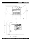
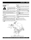
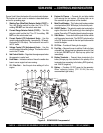
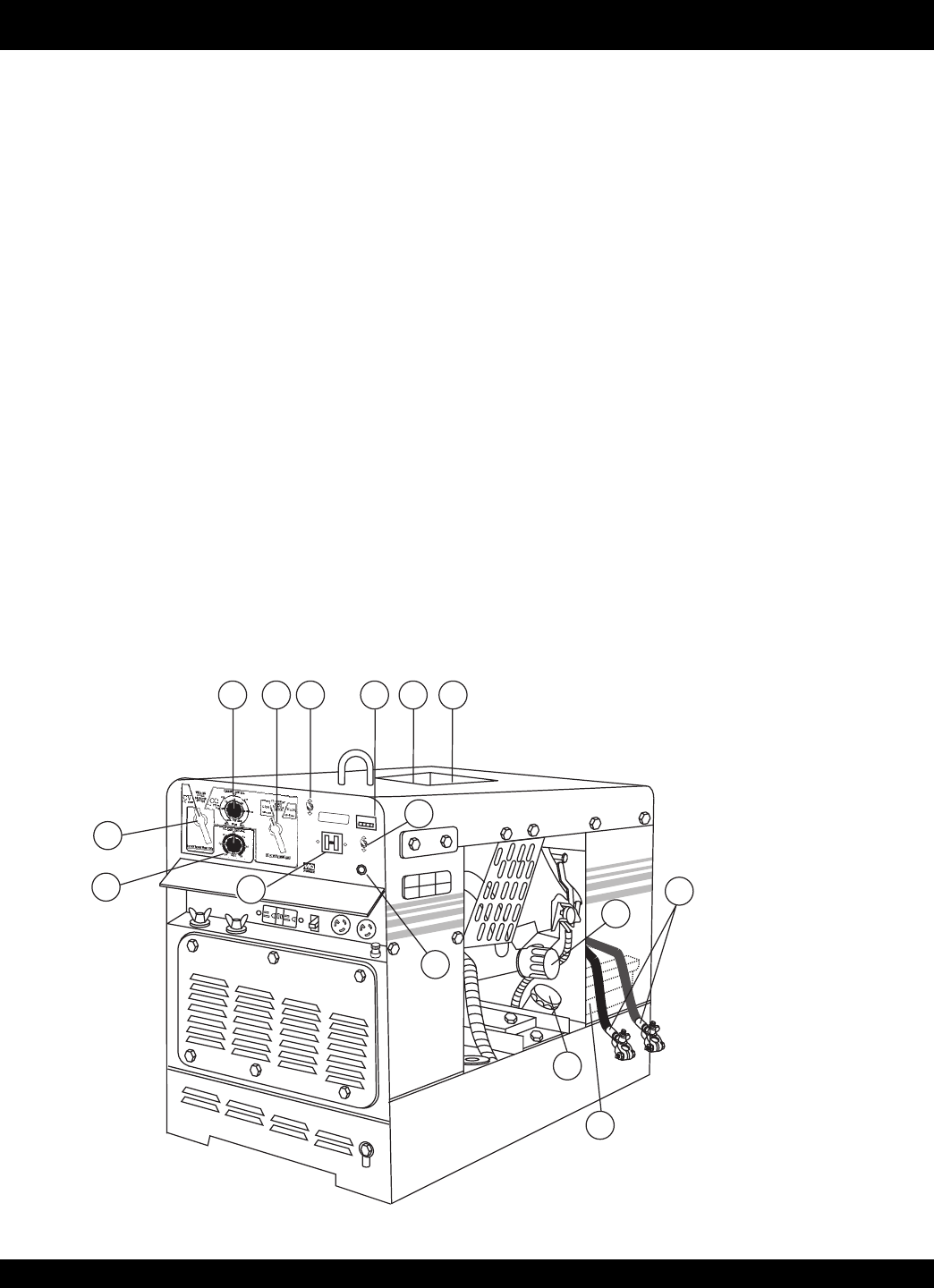
Figures 5 and 6 show the location of the controls and indicators.
The functions of each control or indicator is described below
and on the preceding page.
1. Welding Type (Wire/Stick) Selector Switch (CV/CC) –
Turn this selector switch to either the CV or CC for
welding. DO NOT turn this switch under load.
2. Current Range Selector Switch (CV/CC) – Turn this
selector switch to either the CV or CC for welding. DO
NOT turn this switch under load.
3. Current Control (CC) Adjustment Knob – Use this
control to adjust welding current. Low scale (50~120 amps),
High scale (90~250 amps). This function will not work in
the CV mode.
4. Voltage Control (CV) Adjustment Knob – Use this
control to adjust the welding voltage. This function will not
work in the CC mode.
5. Idle Control Switch – Regulates the engine speed when
the generator is under load.
6. Hour Meter – Indicates number of hours the welder has
been in use or engine has been running.
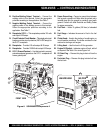
7. Oil Filler Port – Use this port when adding oil to the
engine.
8. Engine Air Cleaner – Prevents dirt and other debris
from entering the fuel system. Lift locking latch on air
filter cannister to gain access to filter element.
9. Main Circuit Breaker – This 2-pole circuit breaker provides
circuit protection (265V @30 amps) for the electric parts.
10. ON/OFF Switch – This switch is used to start and stop the
engine. Must be in th ON position (up) when starting the
engine. Place in the OFF position (down) to stop the engine.
11. Start Button – Press and hold this push-button switch
until the engine has started. The ON/OFF switch must be
in the ‘ON’ position in order for the start push-button switch
to start the engine.
12. Oil Filter – Provides oil filtering for the engine.
13. Fuel Cap – Remove this cap to add fuel. Add only clean
unleaded fuel. Always keep an adequate amount of fuel
in the tank. DO NOT top off. Wipe up any spilled fuel
immediately.
14. Battery Terminals – Connect these terminals to the
battery. Always pay close attention to the polarity of the
terminals when connecting to the battery, RED (positive),
and BLACK (negative).
15. Battery – Provides +12 VDC power for the generator.
When replacing battery (12V 35 AH) use only
recommended type battery.
Figure 5. SGW250SS Components 1
MQ POWER
O
N
I
D
L
E
C
O
N
T
R
O
L
O
F
F
ON
O
P
E
R
A
T
I
O
N
S
W
I
T
C
H
OFF
AC
C
I
R
C
U
I
T
B
R
E
A
K
E
R
H
O
N
D
A
POWERED
by
POWERED
by
MQ POWER
S
T
A
R
T
B
U
T
T
O
N
WHISPERWELD
S
G
W
-250S
S
Q
U
A
R
T
Z
H
O
U
R
M
E
T
E
R
MQ POWER
Power Source Professionals.
4
1
3 2
5
6
11
9
10
15
12
7 8
13
14
SGW-250SS — CONTROLS AND INDICATORS