


R2000H RIDE-ON STATIC ROLLER — OPERATION AND PARTS MANUAL — REV. #6 (11/29/10) — PAGE 19
R2000H — ROLLER COMPONENTS
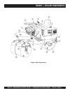
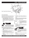
1. Engine – The MQ R2000H ride-on roller uses an 7.1 HP
Honda GX240K1QAE2 air cooled, 4-stroke, single cylinder
gasoline engine. This engine uses unleaded gasoline.
2. Steering Wheel — Use this wheel to steer the roller.
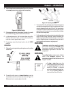
3. Parking Break Lever — Pull the lever upward to set the
parking break. To release the parking break, press and
hold the button on top of the lever and push lever downward.
4. Transmission Control Lever — Push the lever
forward
to make the roller travel in a forward direction, pull the lever
backward
to make the roller travel in a reverse direction.
Maximum travel speed is 5.6 MPH (9.0 KPH). Center
position is neutral, no travel.
5. Documentation Box — Maintain and store
at all times
Operation, Parts, and Engine manuals in this box.
6. Operator's Seat —
A contoured seat that provides visibility
of both front rear drum edges during
operation.
NEVER!
start the roller unless seated in the operator's seat.
7. Water Tank/Cap — Remove filler cap and fill with clean
fresh water. Water tank capacity is 21 gallons (79.5 liters).
If water level is low, add water as necessary.
8. Rear Lifting Point – Attach a crane or suitable lifting
device to this point when lifting of the roller is required.
9. Rear Scrapper – This adjustable rear scrapper blade
helps prevent the buildup of material between the drum
and frame.
10. Rear Roller – This roller is a 32-inch wide
steel drum
with beveled edges (no vibration). The beveled edges
help prevent asphalt marring.
11. Front Lifting Point – Attach a crane or suitable lifting
device to this point when lifting of the roller is required.
12. Front Scrapper – This adjustable rear scrapper blade
helps prevent the buildup of material between the drum
and frame.
13. Front Roller Water Plug – Remove this plug to add
water (ballast) to the front drum. This plug is located on
each side of the split front roller.
14. Front Roller Zerk Fitting – Grease this fitting as
recommended in the maintenance section of this
manual.
15. Steering Zerk Fitting – Grease this fitting as
recommended in the maintenance section of this
manual.
16. Access Panel – Lift this -panel to gain access to the
transmission assembly and battery.
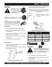
A. Transmission – This roller uses a hydrostatic
pump which provides hydraulic pressure to the
hydraulic drive system. Fill the pump reservoir with
hydrostatic transmission fluid. Fill with Mobil 300,
GM Dextron B or Ford MCZ-41A type transmission
fluid.
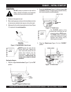
Free Wheel Engagement Pin
The hydrostatic transmission is equipped with a free
wheel engagement pin, which, when actuated, allows
the oil to circulate freely within the roller, thereby
permitting the roller to be moved without the engine
running. This engagement pin is only to be used in
the event the roller is disabled.
This pin is located on the side of the hydrostatic
transmission underneath the acess cover. It is actuated
by pushing the pin inward and placing the locking
clip over the pin to keep it in place.
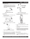
17. Sprinkler Valve Lever – A gravity feed spray bar is
provided on the front and rear of the roller for the wetting
of the roll for asphalt pavement.
Pull
upward on the lever
to
start
the flow of water to the gravity feed system.
Push
the lever
downward
to
stop
the flow of water.
18. Front Roller – This roller is a
split
28-inch wide
steel
drum
with beveled edges (no vibration). The beveled
edges help prevent asphalt marring.
19. Rear Roller Water Plug – Remove this plug to add
water (ballast) to the rear drum. This plug is located on
the chain-side of the roller. It is shown here for clarity
only.
B. Battery – Provides +12VDC to the electrical
system. Replace only with recommended type
battery, see specification Table 1.
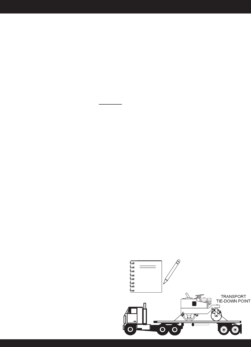
NOTE
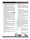
Tie-Down Transport Points –
Attach a chain or suitable tie-down
device to these points when
transporting of the roller is
required.