


PAGE 14 — GA-3.6RZ2 A.C. GENERATOR— PARTS & OPERATION MANUAL — REV. #2 (03/05/01)
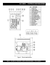
GA-3.6RZ2 — INSTRUMENTATION
Power Outlets
The generator has the following 120/240 volt 60 Hz (single-
phase) receptacles.
l
Single Phase
One Duplex NEMA (GFCI) 5-20R (120V, 20 Amp)
One Twist Lock NEMA L5-30R (120V, 30 Amp)
One Twist Lock NEMA L6-20R (240V, 20 Amp)
Main Circuit Breaker (2-Pole 120/240V 60 Hz)
This 2-pole 21 amp breaker protects the generator from short
circuiting or overloading from the 120/240V 60 Hz single
phase load.
Idle Control Switch
This unit is provided with an automatic idle control for noise
suppression and reduced fuel consumption. The automatic
idle control automatically engages under a no-load condition.
With the automatic idle control switched “ON”, the engine
revolutions will automatically drop to about 2600 rpm (low-
speed operation) within 3 seconds after the load stops. When
the operation is resumed, the engine speed is automatically
increased to about 3600 rpm (high-speed operation) as soon
as the load is connected.
Fuel Gauge
The fuel gauge is located on the fuel tank and allows easy
monitoring of the fuel level.
AC Voltmeter
This voltmeter indicates (with a mark) the rated 60 Hz, single
phase output voltage. In addition the voltmeter can also be
used as a diagnostic tool.
If the voltmeter indicator (needle) is below the rated voltage,
engine problems may exist (low/high RPM's). To prevent
damage to the generator or power tools turn the generator
OFF and consult your authorized Multiquip service dealer.
Operation Switch
This switch must be in the ON position (up) for normal
operation.
CAUTION :
When using a combination of dual
receptacles, total load should not exceed
the rated capacity of the generating.
Start Switch
Push this switch to start the engine (electric start only). If a
recoil starter is used, pull the starter rope to start the engine.
Make sure the operation switch is in the ON position (up),
otherwise engine will not start.
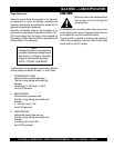
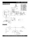
Full Power Switch
The unit is provided with a full power switch. Figures 2 and
3 show simplified wiring diagrams of the dual voltage system.
When the full power switch is in the 120 volt (up) position,
you can take up
full rated power
of the generator at 120
volts from the single duplex receptacle, single locking type
120 volt receptacle, or a combination of these receptacles
as long as the total load does not exceed the generating set
capacity.
Figure 2. 120 V Simplified Diagram (Switch Up)
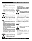
When the full power switch is in the 240 volt (down) position,
you can take up to half of the rated power of the generating
set at 120 volts from the duplex receptacle and up to half of
the rated power of the set at 120 volts from the locking type
120 volt receptacle; or full rated power of the set at 240
volts from the locking type 240 volt receptacle.
NOTE
When the full power switch is in the 120 volt
position, the locking type 240 volt receptacle
cannot be used.
Figure 3. 240 V Simplified Diagram (Switch Dn.)