


DCA45USI2 60 HZ GENERATOR • OPERATION AND PARTS MANUAL — REV. #0 (01/12/11) — PAGE 35
GENERATOR START-UP PROCEDURE
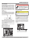
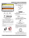
the problem. If the engine is running smoothly, place
the engine speed switch (Figure 42) in the HIGH (up)
position.
Figure 42. Engine Speed Switch (High)
5. Verify that the engine running status LED on the
MPEC module (Figure 43) is lit (ON) after the engine
has started.
Figure 43. Engine Running (LED ON)
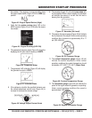
6. The generator’s frequency meter (Figure 44) should be
displaying the 50 cycle output frequency in HERTZ.
Figure 44. Frequency Meter
7. The generator’s AC-voltmeter (Figure 45) will display
the generator’s output in VOLTS.
Figure 45. Voltmeter Meter
8. If the voltage is not within the specifi ed tolerance use
the voltage adjustment control knob (Figure 46) to
increase or decrease the desired voltage.
Figure 46. Voltage Adjust Control Knob
9. The ammeter (Figure 47) will indicate zero amps with
no load applied. When a load is applied, the ammeter
will indicate the amount of current that the load is
drawing from the generator.
Figure 47. Ammeter (No Load)
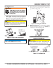
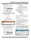
10. The engine oil pressure gauge (Figure 48) will indicate
the oil pressure of the engine. Under normal operating
conditions the oil pressure is approximately 42 to 71
psi. (290~490 kPa).
Figure 48. Oil Pressure Gauge
11. The coolant temperature gauge (Figure 49) will
indicate the coolant temperature. Under normal
operating conditions the coolant temperature should
be between 167°~203°F (75°~95°C) (Green Zone).
Figure 49. Coolant Temperature Gauge
12. The tachometer gauge (Figure 50) will indicate the
speed of the engine when the generator is operating.
Under normal operating conditions this speed is
approximately 1800 RPM’s.
Figure 50. Engine Tachometer Gauge