


DCA45SSK/KU3 60 HZ GENERATOR • OPERATION AND PARTS MANUAL — REV. #0 (12/15/11) — PAGE 19
GENERATOR CONTROL PANEL
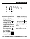
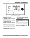
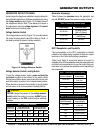
Figure 5. Generator Control Panel
OFF
W-U
V-W
U-V
START
STOP
RUN
DECREASE
INCREASE
1 2 3
4
5 6
The definitions below describe the controls and functions
of the Generator Control Panel (Figure 5).
1. Frequency Meter — Indicates the output frequency
in hertz (Hz). Normally 60 Hz.
2. AC Ammeter — Indicates the amount of current the
load is drawing from the generator per leg selected by
the ammeter phase-selector switch.
3. AC Voltmeter — Indicates the output voltage present
at the U,V, and W output terminal lugs.
4. Ammeter Change-Over Switch — This switch allows
the AC ammeter to indicate the current flowing to the
load connected to any phase of the output terminals,
or to be switched off. This switch does not effect the
generator output in any fashion, it is for current reading
only.
5. Voltage Regulator Control — Allows ±15% manual
adjustment of the generator’s output voltage.
6. Main Circuit Breaker—This three-pole, 125A main
breaker is provided to protect the the U,V, and W Output
Terminal Lugs from overload.
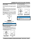
NOTICE
Remember the overcurrent relay monitors the current
flowing from the U,V, and W output terminal lugs to
the load.
In the event of a short circuit or over current condition,
it will automatically trip the 125 amp main breaker.
To restore power to the output terminal panel, press
the reset button on the overcurrent relay and place the
main circuit breaker in the closed position (ON).