


PAGE 30 — DCA-36SPX— OPERATION AND PARTS MANUAL — REV. #1 (04/14/10)
UOV Terminal Output Voltages
240/120V output voltages can be obtained using the
Output
Terminal Lugs
..
The voltage regulator (VR) allows the user to increase or
decrease the selected voltage.
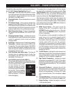
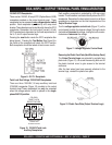
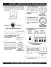
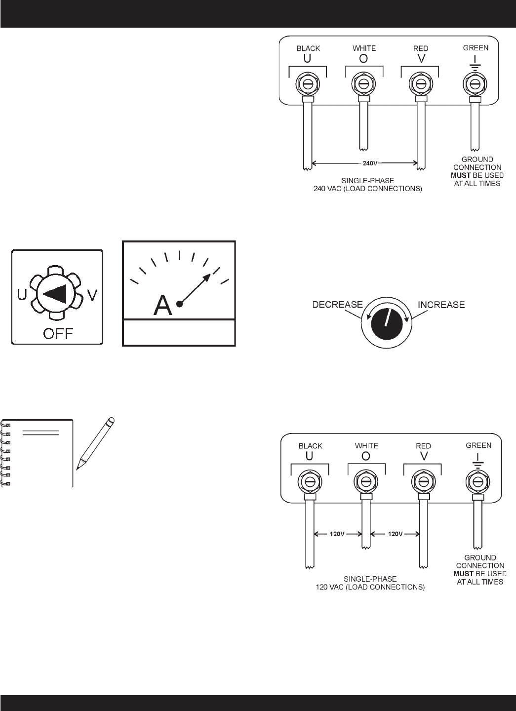
1Ø 240 Output Terminal Lug Voltages
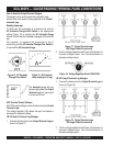
1. Connect the load wires to the
Output Terminal Lugs
as
shown in (Figure 17)
Figure 17. Output Terminal Lugs
240 Single Phase Connections
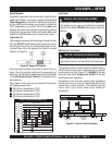
2. Turn the voltage regulator knob (Figure 18) clockwise to
increase voltage output, turn counterclockwise to
decrease voltage output.
Figure 18. Voltage Regulator Knob (139V/240V)
2. Turn the voltage regulator knob (Figure 18) clockwise to
increase voltage output, turn counterclockwise to
decrease voltage output.
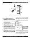
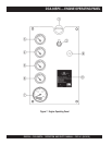
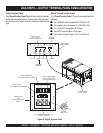
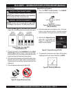
How to Read the Output Terminal Gauges.
The gauges on the control panel are provided to help
observe how much power is being supplied at the
Output
terminals lugs
.
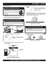
Figure 16. AC Ammeter
(Amp reading on U lug)
Figure 15. AC Ammeter
Change-Over Switch
Reading Amperage
To determine the amperage at a terminal lug, set the
AC Ammeter Change-Over
Switch
to the appropriate
setting (Figure 15) to activate the
AC Ammeter Gauge
(Figure 16) and read the available amperage at the terminal
lug.
For example, to measure the amperage at the U
terminal lug, set the
AC Ammeter Change-Over Switch
to
U and read the AC Ammeter Gauge.
The
ammeter
gauge will only
show a reading when the
Output
Terminal Lugs
are connected
to a load and in use.
NOTE
DCA-36SPX — GAUGE READING/ TERMINAL PANEL CONNECTIONS
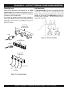
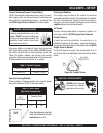
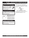
1Ø 120 Output Terminal Lug Voltages
1. Connect the load wires to the
Output Terminal Lugs
as
shown in (Figure 19)
Figure 19. Output Terminal Lugs
120 Single Phase Connections