


DCA-125USJ — OPERATION AND PARTS MANUAL — REV. #2 (01/27/11) — PAGE 37
1
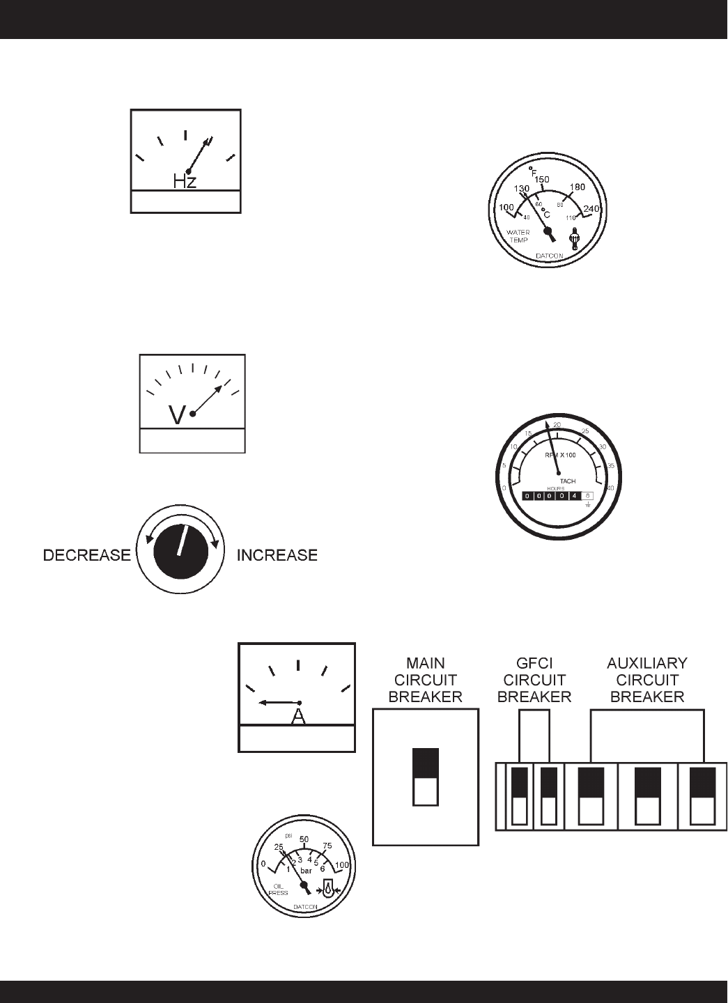
DCA-125USJ — GENERATOR START-UP PROCEDURE (MANUAL)
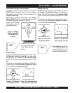
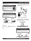
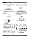
Figure 47. Voltage Adjust
Control Knob
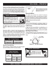
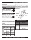
Figure 48. Ammeter (No Load)
11. The ammeter (Figure 48) will
indicate zero amps with no load
applied. When a load is applied,
the ammeter will indicate the
amount of current that the load is
drawing from the generator.
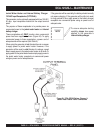
10. The generator's AC-voltmeter (Figure 46) will display the
generator’s output in VOLTS. If the voltage is not within
the specified tolerance, use the voltage adjustment
control knob (Figure 47) to increase or decrease the
desired voltage.
Figure 46. Voltmeter
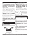
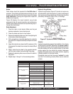
Figure 45. Frequency Meter (Hz)
9. The generator's frequency meter (Figure 45) should be
displaying the 60 cycle output frequency in HERTZ.
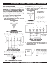
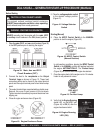
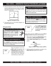
Figure 51. Engine Tachometer Gauge
14. The
tachometer gauge
(Figure 51) will indicate the
speed of the engine when the generator is operating.
Under normal operating conditions this speed is
approximately 1800 RPM’s.
13. The
coolant temperature gauge
(Figure 50) will indicate
the coolant temperature. Under normal operating
conditions the coolant temperature should be between
165 and 215 degrees Fahrenheit (
Green Zone
).
Figure 50. Coolant Temperature Gauge
12. The engine oil pressure gauge
(Figure 49) will indicate the oil
pressure (kg/ cm
2
)
of the engine.
Under normal operating conditions
the oil pressure is approximately
35~65 PSI.
Figure 49. Oil Pressure Gauge
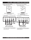
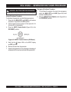
Figure 52. Main, Aux. and GFCI
Circuit Breakers (ON)
15. Place the
main
,
GFCI
, and
aux
. circuit breakers in the
ON position (Figure 52).