


10
• Slightly overlap each previous cleared path.
• Follow the precautions found under the heading To
Stop Engine to prevent possible freeze-up.
• Clean the snow thrower thoroughly after each use.
SECTION 6: MAKING ADJUSTMENTS
WARNING: NEVER attempt to clean chute
or make any adjustments while engine is
running.
Chute Assembly Adjustment
The distance snow is thrown can be adjusted by
adjusting the angle of the chute assembly. Refer to
Chute Tilt Control in Section 4 of this manual.
Chute Directional Control
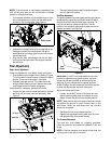
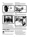
Support Bracket Adjustment
If the spiral at the base of the chute directional control
isn’t fully engaging with the notches in the lower chute
assembly, the support bracket can be adjusted inward
or outward as follows:
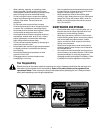
• Loosen, but do NOT remove the two hex nuts
which secure the chute directional control support
bracket to the snow thrower housing. See Figure 9.
Figure 9
• Adjust the support bracket inward or outward so
that the spiral is fully engaged in the notches on the
chute before retightening the hex nuts.
Skid Shoe Adjustment
The space between the shave plate and the ground can
be adjusted by raising or lowering the skid shoes. Refer
to Skid Shoe Adjustment in Section 3 of this manual.
Auger Control Adjustment
Refer to the information found under the heading Final
Adjustments in Section 3 of this manual to adjust the
auger control.
Traction Control Adjustment
Refer to the information found under the heading Final
Adjustments in Section 3 of this manual to adjust the
traction control. If you are uncertain that you have
reached the correct adjustment, proceed as follows:
WARNING: Drain the gasoline out of your
snow thrower’s engine, of place a piece
of plastic film under the gas cap to avoid
spillage BEFORE beginning to perform
this adjustment.
• Tip the snow thrower forward, allowing it to rest on
the auger housing.
• Remove the frame cover underneath the snow
thrower by removing sixself-tapping screws.
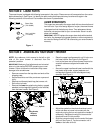
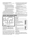
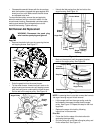
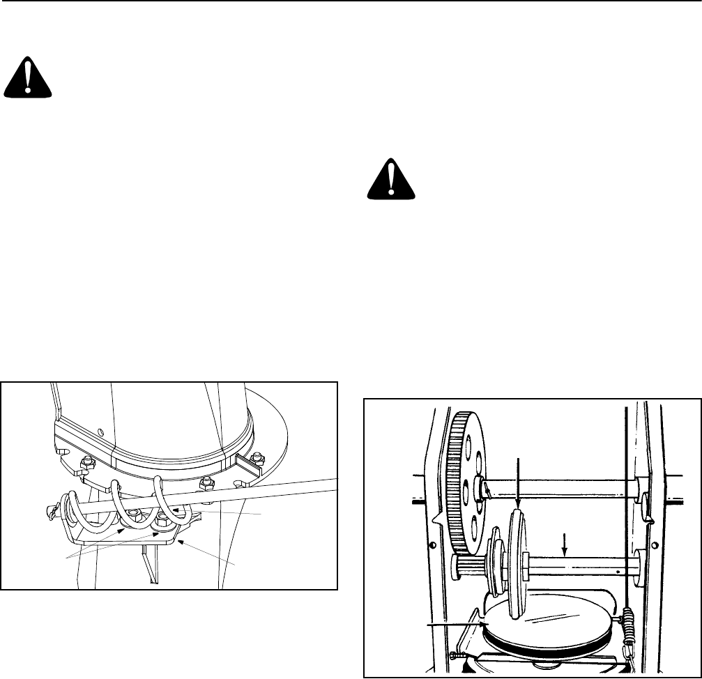
With the traction control released, there must be
clearance between the friction wheel and the drive plate
in all positions of the shift lever.
With the traction control engaged, the friction wheel
must contact the drive plate. See Figure 10.
Figure 10
If adjustment is necessary:
• Loosenthejamnutonthetractiondrivecableand
thread the cable in or out as necessary.
• Retighten the jam nut to secure the cable when
correct adjustment is reached.
• Reassemble the frame cover.
NOTE:
If you placed plastic film under the gas cap, be
certain to remove it before operating the snow thrower.
Hex Nuts
Support Bracket
Spiral
Friction
Wheel
Gear Shaft
Drive
Plate