


7
Figure 3-6
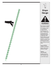
3
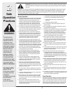
WARNING
NOTE: Make certain
bag is turned right side
out before assembling
(warning label will be on
the outside).
NOTE: Make certain
cables are routed to the
outside of the handle so
they are not in the way
when attaching the grass
catcher.
Never operate mower
unless the hooks on
the grass catcher are
firmly seated on the
pivot rod, and the
rear discharge door
rests firmly against
top of the grass
catcher.
All mowers are
equipped with a rear
protective guard. The
guard helps eliminate
projectiles thrown
by the blade from
injuring the operator.
DO NOT REMOVE
THIS GUARD.
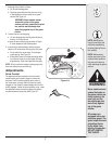
7. Attaching Grass Catcher to Mower
a. Lift the rear discharge door.
b. Place the grass catcher on the pivot rod. Let go
of discharge door so that it rests on the grass
catcher. See Figure 3-5.
WARNING: Never operate mower
unless the hooks on the grass
catcher are firmly seated on the pivot
rod, and the rear discharge door
rests firmly against top of the grass
catcher.
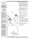
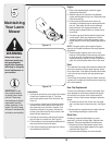
8. To install the rear mulching plug.
a. Lift rear discharge door and lift grass catcher up
and out, off of the pivot rod.
b. Insert the rear mulching plug as shown in Figure
3-4 and release the rear discharge door.
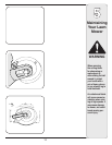
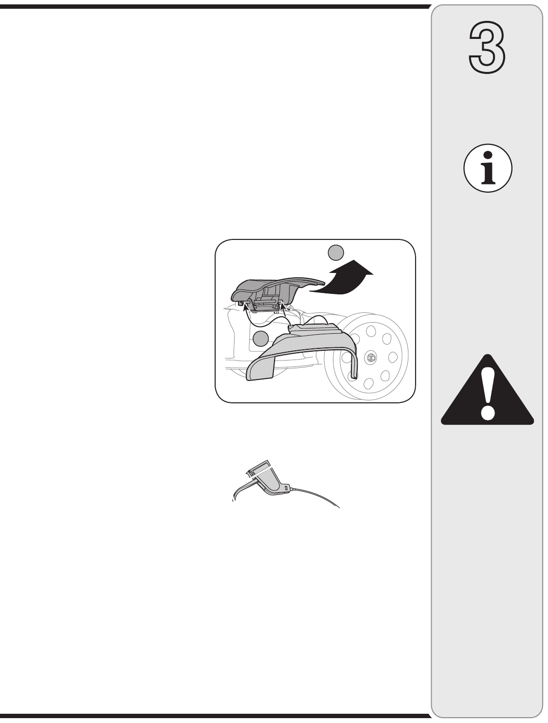
9. If converting to side discharge, make sure grass
catcher is off unit and rear mulching plug is in place.
a. On the side of the mower deck, lift the hinged
mulching plug. See Figure 3-6.
b. Slide the two hooks on the side discharge deflec-
tor under the hinge pin on the hinged mulching
plug assembly. Lower the hinged mulching plug.
NOTE: Do not remove the hinged mulching plug at any
time, even when you are not mulching.
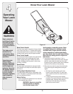
Adjustments
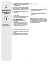
Drive Control
The adjustment wheel is located in the drive control
handle housing and is used to tighten or loosen the
drive belt. You will need to adjust the drive control if
the mower does not propel itself with the drive control
engaged or if the mower’s wheels hesitate with the drive
control engaged. If either of these conditions occur, rotate
the adjustment wheel clockwise to tighten the cable or
counterclockwise to loosen the cable, Figure 3-7.
A
B