


7
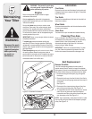
Figure 3–4: Remove hardware from lower handle.
3
Assembly
NOTE: Stand behind
the tiller as if you were
going to operate it. Your
right hand corresponds
to right side of
tiller; your left hand
corresponds to
left side of tiller.
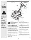
IMPORTANT
This unit is shipped
without gasoline or
oil in the engine. Fill
up gasoline and oil
as instructed in the
accompanying engine
manual BEFORE
operating your tiller.
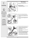
7. Locate the carriage bolt, bell washer and
hand knob packed with your unit.
8. Insert the carriage bolt through the welded
bracket on the handle, bell washer, handle
brace and into the hand knob.
See Figure 3–4.
9. Select one of the three handle height
positions (three notches in welded handle
bracket) and tighten the hand knob to secure
the handle in the desired position.
Figure 3–4. Return to lower handle and
tighten the hex bolt securely
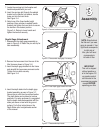
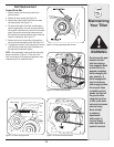
Depth Gage Attachment
1. Disassemble the depth gage assembly as
seen in Figure 3–5. Retain the pin and clip for
later reassembly.
Figure 3–5: Disassemble depth gage if necessary.
Figure 3–6: Insert depth gage bracket into frame.
Figure 3–7: Reassemble depth stake.
2. Remove the two screws from the rear of the
tiller frame as shown in Figure 3–6.
3. Insert the depth gage bracket into the frame
and reinstall the two screws removed earlier.
Tighten the hex bolts securely.
See Figure 3–6.
4. Insert the depth stake into the depth gage
bracket assembly as seen in Figure 3–7.
Secure the pin with the clip removed earlier.
The depth stake can be placed at various
positions. For setup purposes it is suggested
that the depth stake be assembled with the
stake just above or level with the ground
surface. For further instructions on the
Depth Stake refer to adjustments section
of this manual.