


10
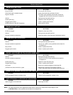
MAINTENANCE SCHEDULE
Perform these required maintenance procedures at the
frequency stated in the table. These procedures should also be
a part of any seasonal tune-up.
NOTE: Some maintenance procedures may require special
tools or skills. If you are unsure about these procedures,
take your unit to a MTD or other qualified service dealer.
Call 1-800-800-7310 for more information.
NOTE: Maintenance, replacement, or repair of the emission
control devices and system may be performed by a
MTD or other qualified service dealer. Call 1-800-800-
7310 for more information.
FREQUENCY MAINTENANCE REQUIRED REFER TO
Before starting engine
Fill fuel tank with fresh fuel
Check oil
Page 7
Page 10
Every 10 hours Clean and re-oil air filter Page 11
First change at 10 hours
Second change at 25 hours
Every 25 hours thereafter
Change oil
Change oil
Clean spark arrestor
Page 11
Page 11
Page 14
Every 25 hours Check spark plug condition and gap Page 14
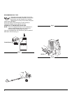
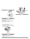
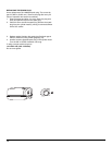
CHECKING THE OIL LEVEL
The importance of checking and maintaining the proper oil
level in the crankcase cannot be overemphasized. Check oil
before each use:
1. Stop the engine and allow oil to drain into the crankcase.
2. Place the unit on a flat, level surface to get a proper oil
level reading (Fig. 9).
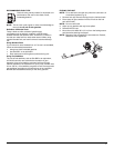
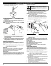
3. Keep dirt, grass clippings and other debris out of the
engine. Clean the area around the oil fill plug/dipstick
before removing it.
4. Remove the oil fill plug/dipstick and wipe off oil. Reinsert it
all the way back in.
5. Remove the oil fill plug/dipstick and check the oil level. Oil
should be up to the top of the dipstick (Fig. 15).
6. If the level is low, add a small amount of oil to the oil fill hole
and recheck (Fig. 16). Repeat this procedure until the oil level
reaches the top of the dipstick.
NOTE: Do not overfill the unit.
MAINTENANCE AND REPAIR INSTRUCTIONS
WARNING: To prevent serious injury, never
perform maintenance or repairs with unit running.
Always service and repair a cool unit. Disconnect the
spark plug wire to ensure that the unit cannot start.
CAUTION: To prevent extensive engine wear
and damage to the unit, always maintain the proper
oil level in the crankcase. Never operate the unit
with the oil level below the bottom of the dipstick.
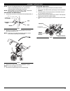
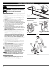
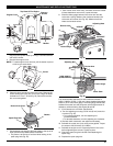
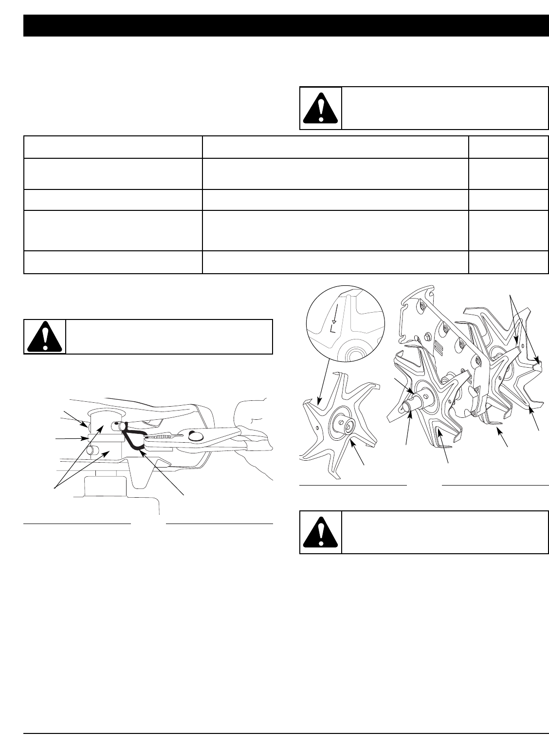
Fig. 12
Clevis Pin Clip
Felt
Washer
Shaft
Felt
Washer
Tine
Hubs
Stagger Tips
R
R
L
L
Clevis Pin
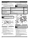
TINE REMOVAL AND REPLACEMENT
Replace all four (4) tines at the same time, because they will
wear evenly through normal use. Work on one side at a time.
1. Put the On/Off Stop Control in the STOP (O) position
and disconnect the spark plug wire.
2. Remove the clevis pin clips and clevis pins (Fig. 11).
3. Remove the tines and felt washers from the shaft.
4. Clean and oil the shaft.
5. The tines are stamped with the letter "R" or "L" to
identified their position on each side of the gearbox when
facing the front of the unit.
6. Replace the tines and felt washers onto the shaft with the
hubs on the tines facing each other.
7. Before you reinstall the clevis pins and pin clips, ensure
that the tips on the tines are staggered when compared to
each other (Fig. 12).
8. Repeat this procedure on the opposite side.
NOTE: When installed correctly, there will be an "R" and "L"
tine on both the sides of the gearbox and the tips of
the tines. These letters will line up in the same
direction for each side. It is important that the tines are
installed correctly.
Fig. 11
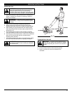
WARNING: To prevent serious personal injury,
always wear heavy gloves when handling the
tines.