


6
pair of pliers to obtain slack in order to hook it into
the control handle. Hold the “Z” fitting with the
pliers, not the cable, to avoid damaging the cable.
NOTE:
The upper hole in the control handle provides
for adjustment in belt tension. Refer to Belt Tension
Adjustment Section of this manual for instructions.
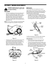
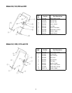
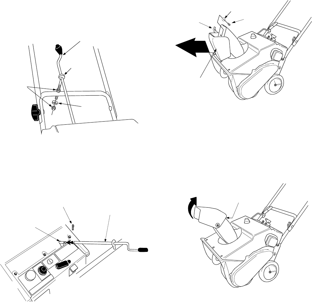
Installing chute crank
Models with optional extended chute crank only
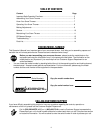
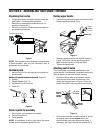
• Thread one 5/16” hex nut all the way onto the
eyebolt. See Figure 5. All necessary hardware is
included in the hardware pack shipped with your
unit. See Figure 2 for more details.
• Slide the eyebolt onto the chute crank. Insert
eyebolt into the hole in the lower handle.
Figure 5
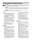
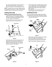
• Insert the chute crank into the coupler at the top
rightsideofthesnowthrower.SeeFigure6.
• Rotate the crank to align holes, and insert the
cotter pin. Bend ends of cotter pin in opposite
directions to secure. See Figure 6.
Figure 6
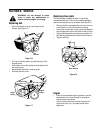
• Secure eyebolt with 5/16” saddle washer and hex
nut. The cupped side of washer goes against the
handle. Adjust lower hex nut until the eyebolt is
positioned so that the chute crank turns freely
(does not bind).
• Move upper hex nut down against the lower
handle. Tighten lower hex nut securely.
Assembling the chute
The snow thrower has been shipped with the upper
chute pivoted all the way down. Assemble as follows:
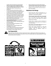
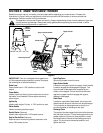
• Turn the chute crank until the chute faces straight
to the front. See Figure 7 .
Figure 7
• Remove the hand knob, flat washer and carriage
bolt from the upper chute. See Figure 7.
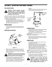
• Pivottheupperchuteupsothatthereisnogap
between the upper and the lower chute. See
Figure 8. Secure with hardware just removed.
Figure 8
Hex
Nuts
Eye Bolt
Chute Crank
Saddle
Washer
Cotter Pin
Chute Crank
Coupler
Upper
Chute
Hand
Knob
Flat
Washer
Carriage
Bolt
Front
No
Gap
Pivot
chute
upper