


6
SECTION 5: ASSEMBLY INSTRUCTIONS
NOTE: Reference to right or left side of the snow
thrower can be determined from behind the unit
in the operating position.
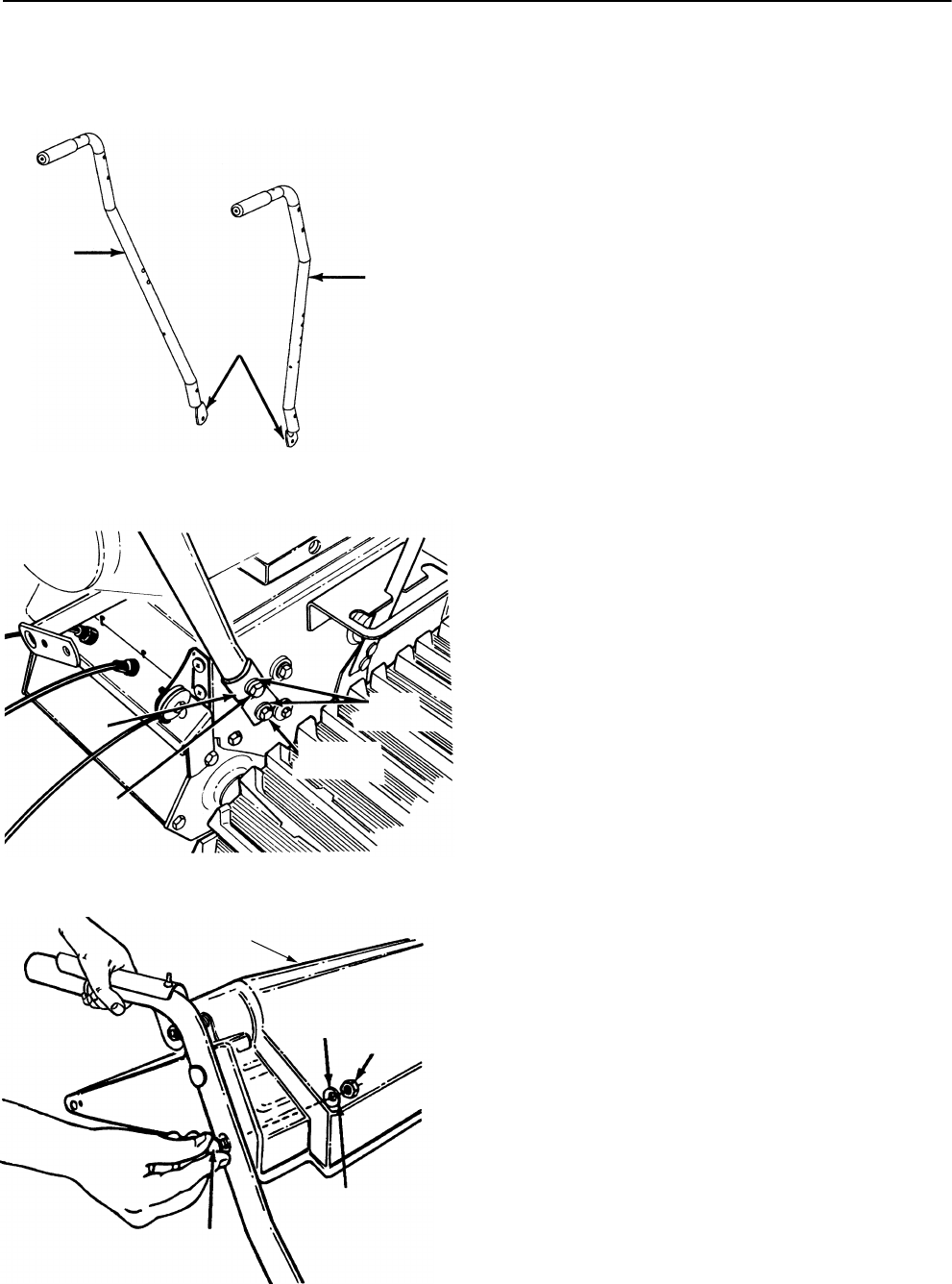
Figure 2
Figure 3
Figure 4
UNPACKING
1. Remove staples or break glue on the top flaps of
the carton. Remove any loose parts included
with unit (i.e., operator’s manual, etc.).
2. Cut along dotted lines and lay end of carton
down flat. Remove packing material.
3. Roll unit out of carton. Check carton thoroughly
for loose parts.
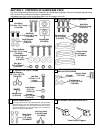
4. Lay out the hardware according to the illustration
on page 5 for identification purposes.
Tools Required for Assembly:
(1) 3/8" Wrench or Adjustable
(2) 7/16" Wrenches or Adjustable
(1) 1/2" Wrench or Adjustable
(1) Pair of Pliers
(1) Phillips Screwdriver
ATTACHING THE HANDLE ASSEMBLY
(Hardware A)
1. Stretch out control cables and place on the floor
behind unit.
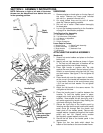
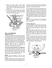
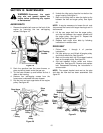
2. Identify left and right handles as shown in figure
2. The flats on the lower part of handles will be
placed against the snow thrower housing.
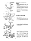
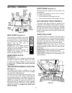
3. Place right handle in position with flat side
against the snow thrower. Secure bottom hole in
handle to snow thrower using hex bolt 3/4" long
and lock washer. See figure 3. Do not tighten at
this time.
4. Place handle tab over the upper hole in handle,
so the curve in the handle tab matches the curve
in the handle. Secure to the snow thrower using
1-3/4" hex bolt and lock washer. Do not tighten
at this time.
5. Attach the left handle in the same manner. Do
not tighten at this time.
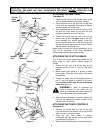
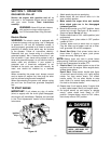
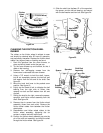
6. Place the handle panel in position between the
handles. To hold the handle panel in place,
engage both clutch grips (hold them against the
handles). Now release the left hand grip, and it
will remain against the handle. Keep holding the
right hand clutch grip. See figure 4.
7. Secure the right side of the handle panel by
inserting carriage bolt through handle and handle
panel (must go through both the plastic and
metal parts of the handle panel). Secure with
cupped washer (cupped side against the handle
panel) and hex nut. Repeat using another
carriage bolt, cupped washer and hex nut.
8. Secure the left side of the handle panel in the
same manner.
9. Tighten the four hex bolts which attach the
bottom of the handles to the snow thrower frame.
Flat
Right
Handle
Left
Handle
Hex
Bolt 1-3/4"
Long
Hex Bolt
3/4" Long
Lock
Washers
Handle
Tab
Handle Panel
Cupped
Washer
Hex
Nut
Carriage
Bolt
NOTE:
Place the cupped
side against the
handle panel.
Loose Parts in Carton:
(1) Handle Panel (1) Chute Crank Assembly
(1) Chute Assembly (1) Shift Rod
(1) Right Handle (1) Hardware Pack
(1) Left Handle