


8
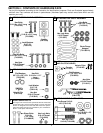
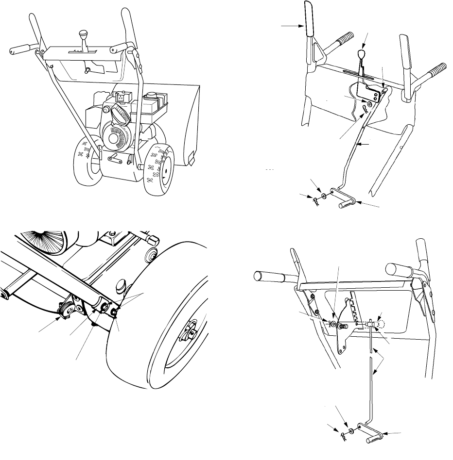
Figure 9
Figure 10
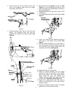
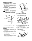
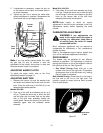
ATTACHING SHIFT ROD
(Hardware D)
1. Place the shift lever in the fifth (5) or the fastest
forward speed position.
2.
Models 642, 662
: Rotate the shift arm
assembly counter clockwise, as far as it will go.
Insert the shift rod through the shift arm
assembly. When installed the shift arm
assembly should point to the right. Secure with
flat washer and hairpin clip. See Figure 11.
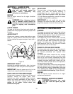
Model 614, 644, 664:
Rotate the shift arm
assembly clockwise as far as it will go. Insert
the shift rod through the shift arm assembly.
When installed, the shift arm assembly should
point left. Secure with flat washer and hairpin
clip. See Figure 12.
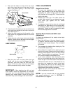
Figure 11
Figure 12
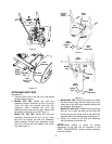
3.
Models 642, 662:
Thread the ferrule up or down
the shift rod and align with the lower hole on the
wider side of the shift lever assembly behind the
handle panel. See Figure 11.
Model 614, 644, 664:
Thread the ferrule onto the
shift rod, up or down the shift rod and align with
the far hole on the narrow side of the shift lever
assembly behind the handle panel. See Figure 12.
4. Secure the ferrule to the shift arm assembly
with flat washer and hairpin clip.
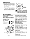
NOTE:
Make certain to check for correct
adjustment of the shift rod as instructed in the
FINAL ADJUSTMENTS section before operating
the snow thrower.
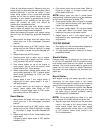
Handle
Bolt 1-3/4”
3/4” Long
Washers
Hex Bolt
Tab
Long
Hex
Lock
Cable
Roller
Guide
Traction
Clutch
Drive
Shift
Lever
Ferrule
Hairpin
Clip
Flat
Washer
Hairpin
Clip
Shift
Arm
Assembly
Flat
Washer
Shift
Rod
Flat
Washer
Shift
Lever
Hairpin
Clip
Ferrule
Flat
Washer
Hairpin
Clip
Shift
Rod
Shift
Arm
Assembly