


11
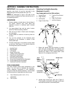
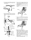
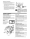
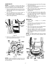
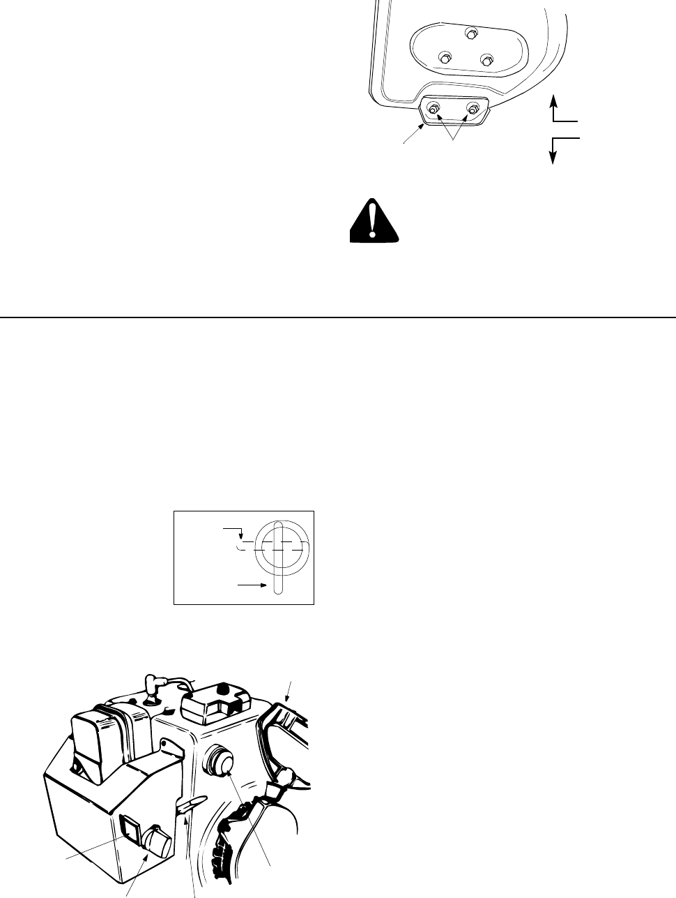
Adjusting The Skid Shoes
The space between the shave plate and the ground
can be adjusted by adjusting the skid shoes.
1. Place skid shoes in the low position to remove
snow close to the ground. Place skid shoes in a
higher position to remove snow from uneven
ground. See Figure 19.
2. Adjust skid shoes by loosening the four hex nuts
and carriage bolts and moving skid shoes to
desired position. Make certain the entire bottom
surface of skid shoe is against the ground to
avoid uneven wear on the skid shoes. Retighten
nuts and bolts securely.
Figure 19
WARNING: It is not recommended
that you operate this snow thrower on
gravel as loose gravel can be easily
picked up and thrown by the auger
causing an injury and/or damage to the
snow thrower.
SECTION 6: CONTROLS
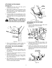
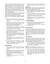
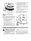
THROTTLE CONTROL
The throttle control is located on the engine. It regulates
the speed of the engine. See Figure 21
SAFETY IGNITION SWITCH
The ignition key must be inserted in the switch before
the unit will start. Remove the ignition key when
snow thrower is not in use
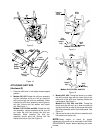
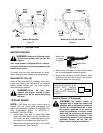
FUEL SHUT-OFF
VALVE
The fuel shut-off valve,
located under fuel tank,
controls fuel flow from
tank. (If equipped)
See Figure 20.
Figure 21
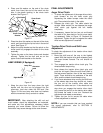
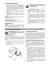
SHIFT LEVER
(See Figure 22 for Model 642 and 662. See Figure
23 for Models 614, 644, 664, and 6A4)
The shift lever is located in the center of the handle
panel. The shift lever may be moved into one of six
positions. Run engine with throttle in the fast
position. Use the shift lever to determine ground
speed.
Forward—Five forward speeds: position one (1) is
the slowest; position five (5) is the fastest.
Reverse—One reverse (R) speed.
NOTE: Model 614, 644, 664, and 6A4 has seven
positions.
AUGER DRIVE CLUTCH
(See Figure 22 for Model 642 and 662. See Figure
23 for Models 614, 644, 664, and 6A4)
The auger drive clutch is located on the left handle.
Squeeze the auger drive clutch against the handle to
engage the augers. Release to stop the snow
throwing action.
TRACTION DRIVE CLUTCH
(See Figure 22 for Model 642 and 662. See Figure
23 for Models 614, 644, 664, and 6A4)
The traction drive clutch is located on the right
handle. Squeeze the traction drive clutch to engage
the wheel drive. Release to stop.
CHUTE CRANK
(See Figure 22 for Model 642 and 662. See Figure
23 for Models 614, 644, 664, and 6A4)
The chute crank is located on left hand side of the
snow thrower.
To change the direction in which snow is thrown,
turn chute crank as follows:
Crank clockwise to discharge to the left.
Crank counterclockwise to discharge to the right.
Skid
Shoe
Hex Nuts
Carriage Bolts
Low Position
High Position
Figure 20
Closed
Open
Ignition
Key
Choke
Throttle
Primer
Starter
Handle