


15
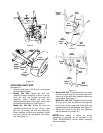
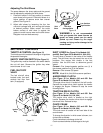
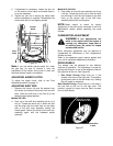
5. If adjustment is necessary, loosen the jam nut
on the traction drive cable, and thread cable in
or out as necessary.
6. Tighten the jam nut to secure the cable when
correct adjustment is reached. Reassemble the
frame cover with six self-tapping screws.
Figure 26
Note: If you had earlier placed plastic film under
the gas cap, be sure to remove it once the
adjustment to the traction drive clutch is done and
the snow thrower frame is re-installed.
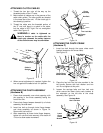
ADJUSTING AUGER CLUTCH
To adjust the auger clutch, refer to the Final
Adjustments section on page 10.
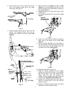
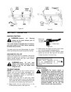
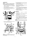
ADJUSTING SHIFT ROD
1. Remove the hairpin clip and flat washer from
the ferrule and remove the ferrule from the shift
lever. Place the shift lever in the fifth (5) or the
fastest forward speed position.
Models 642, 662:
2. Push up on the shift arm assembly as far as it
will go. Thread the ferrule up or down the shift
rod and align with the lower hole on the wider
side of the shift lever assembly behind the
handle panel. Secure the ferrule to the shift arm
assembly again with the hardware earlier
removed.
Model 614, 644, 664:
3. Push down on the shift arm assembly as far as
it will go. Thread the ferrule up or down the shift
rod and align it with the hole closest to the shift
knob on the narrow side of the shift lever
assembly behind the handle panel.
NOTE: Make certain to check for correct
adjustment of the shift rod as instructed in the Final
Adjustments section before operating the snow
thrower.
CARBURETOR ADJUSTMENT
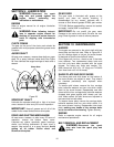
WARNING: If any adjustments are
made to the engine while the engine is
running (e.g. carburetor), keep clear of
all moving parts. Be careful of heated
surfaces and muffler.
Minor carburetor adjustment may be required to
compensate for differences in fuel, temperature,
altitude and load.
Refer to the separate engine manual packed with
your unit for carburetor adjustment information.
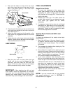
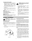
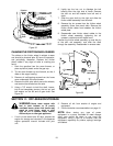
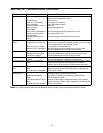
DRIVE WHEELS
The wheels may be adjusted for two different
methods of operation. The adjustment is made by
placing the klick pins in one of two different holes on
the right side of the unit. See Figure 28.
1. One Wheel Driving—Place klick pin in the
outside axle hole on the right side. This position
gives power drive to the left wheel only, making
the unit easier to maneuver.
Both Wheels Driving—Place klick pin in the hole in
the hub next to the rim on the right side. This
position is good for heavy snow as there is power
drive in both wheels.
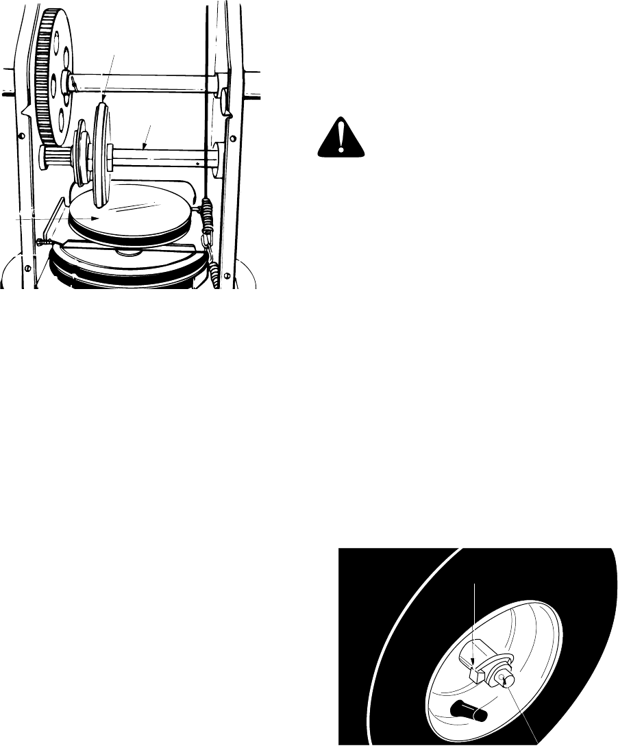
Figure 27
Drive
Plate
Gear
Shaft
Friction
Wheel
Klick Pin in Hole
in Hub Next to Rim
Outside Hole
in Axle