


7
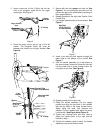
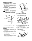
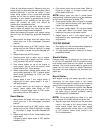
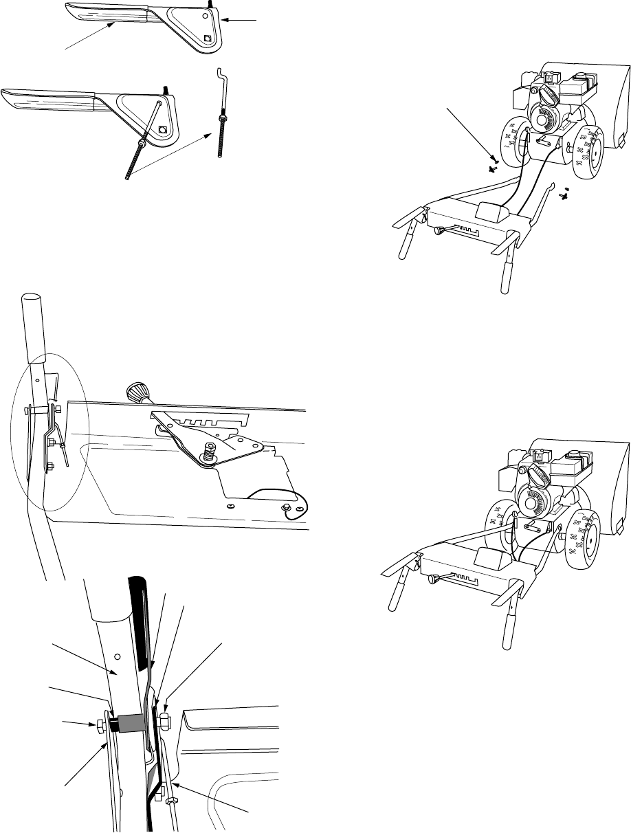
3. Insert curved end of the Z fitting into the top
hole in the triangular metal tab on the auger
control grip. See Figure 5.
Figure 5
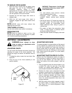
4. Place the auger control grip on top of the left
handle. The triangular metal tab must be
between the handle and the grip bracket.
See
Figure 6.
Figure 6
5. Secure with hex bolt,
spacer
and lock nut.
See
Figure 6
. (Do not overtighten this bolt as it will
prevent the grips from automatically returning to
their upright position.)
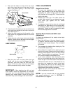
6. Repeat process for the right side Traction Drive
Control Grip.
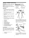
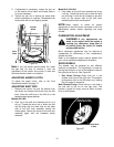
7. Lay handle assembly behind snow thrower.
See
Figure 7.
Figure 7
8. Insert a hex bolt and lock washer through the
lower hole on the bottom of the handle.
See
Figure 7.
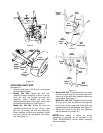
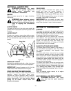
9. Hold the handle assembly up to the bottom of
the snow thrower frame and thread the hex bolt
into the lower hole in snow thrower frame. Do
not tighten at this time.
See Figure 8.
Figure 8
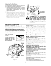
10. Repeat process on the other side.
11. Raise the handle assembly into the upright
position and align the top holes in the handles
with the top holes in the snow thrower frame.
Attach using hex bolts, lock washers and
saddles. (Curve in saddle must match the curve
in the handle.)
See Figure 9 and Figure 10.
12. Tighten four carriage bolts and nuts used to
attach the handle panel to the right and left
handles in step 1.
13. Tighten all hardware used to attach the handle
assembly to the snow thrower frame.
Auger Control
Grip
“Z” Fitting
Triangle
Metal Tab
Auger Control Grip
Clutch Grip Bracket
Handle
Panel
Hex Screw
Spacer
Hex Lock Nut
“Z” Fitting
Left
Handle
(5/16-18)
(5/16-18
x 2.0")
Hex Bolt
& Lock Washer
(5/16-18 x 3/4")