


14
• Set the skid shoes 1/4" below the scraper bar
for normal usage. The skid shoes may be
adjusted upward for hard-packed snow. Adjust
downward when using on gravel or crushed
rock.
• Be certain to follow the precautions listed
under ‘‘To Stop Engine’’ in previous column to
prevent possible freeze-up.
• Clean the snow thrower thoroughly after each
use.
SECTION 8: ADJUSTMENTS
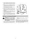
WARNING: Never attempt to clean
chute or make any adjustments while
engine is running.
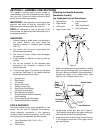
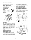
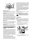
ADJUSTING CHUTE
You can control the distance that snow is thrown by
adjusting the angle of the chute assembly. The
sharper the angle, the shorter the distance snow is
thrown.
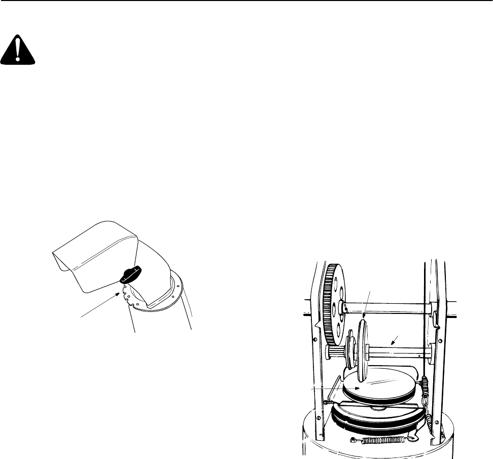
1. To adjust the chute, loosen the hand knob. See
Figure 24.
2. Pivot the top of the chute assembly to the
position desired.
Figure 24
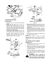
ADJUSTING SKID SHOE
The space between the shave plate and the ground
can be adjusted by adjusting the skid shoe. Slide the
skid shoe upwards and lower the housing to remove
snow close to the ground. Slide skid shoe
downwards and raise the housing to remove snow
from uneven ground like gravel. For more details,
refer to Adjusting the Skid Shoes in section 5.
ADJUSTING TRACTION CONTROL
CLUTCH
Refer to the Final Adjustments section on page 10
for instructions to adjust the traction control clutch. If
you are not sure whether you have been able to
adjust the traction control clutch properly, check as
follows.
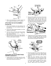
1. Drain the gasoline from the snow thrower or put
a plastic film under the gas cap if the snow
thrower has already been operated. Tip the
snow thrower forward onto the auger housing.
2. Remove the frame cover underneath the snow
thrower by removing the six self-tapping screws.
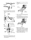
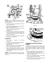
3. With the traction control clutch released, check if
there is clearance between the friction wheel
and the drive plate in all positions of the shift
lever. For correct adjustment there has to be
enough clearance.
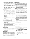
4. With the traction control clutch engaged, check if
the friction wheel is contacting the drive plate.
See Figure 25.
5. If adjustment is necessary, loosen the jam nut
on the traction control cable, and thread cable in
or out as necessary.
6. Tighten the jam nut to secure the cable when
correct adjustment is reached. Reassemble the
frame cover with six self-tapping screws.
Figure 25
Note: If you had earlier placed plastic film under
the gas cap, be sure to remove it once the
adjustment to the traction control clutch is done and
the snow thrower frame is re-installed.
ADJUSTING AUGER CLUTCH
To adjust the auger clutch, refer to the Final
Adjustments in section 5.
Hand
Knob
Drive
Plate
Gear
Shaft
Friction
Wheel