


10
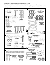
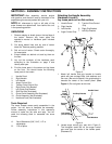
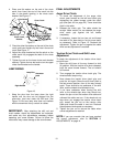
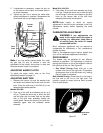
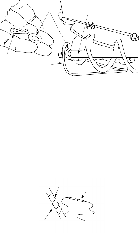
4. Place one flat washer on the end of the chute
crank, then insert the end of the crank into the
hole in the plastic bushing in the chute crank
bracket. See Figure 17.
Figure 17
5. Place the other flat washer on the end of the chute
crank, and insert hairpin clip into hole in the end of
crank. See Figure 17.
6. Adjust the chute bracket so that the spiral on the
chute crank fully engages the teeth on the chute
assembly.
7. Tighten the nuts on the lower chute crank bracket
securely. Tighten the hex bolt and nut on the upper
chute crank bracket on the handle.
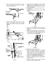
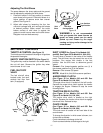
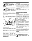
LAMP WIRING
Figure 18
1. Wrap the wire from the lamp down the right
handle until the wire can be plugged into the
alternator lead wire under the fuel tank. See
Figure 18. Be sure lamp wire does not interfere
with the movement of any controls or cables.
IMPORTANT:
After attaching the shift rod and
clutch cables, check the adjustments as instructed,
and make any final adjustments necessary before
operating your snow thrower. Failure to follow the
instructions may cause damage to the snow thrower.
FINAL ADJUSTMENTS
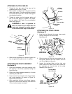
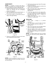
Auger Drive Clutch
1. To check the adjustment of the auger drive
clutch, push forward on the left hand clutch grip
depressing the rubber bumper under the clutch
grip (See part #13 on page 22). There should be
slack in the cable.
2. Release the clutch grip. The cable should be
straight. Make certain you can depress the auger
drive clutch grip against the left handle
completely.
3. If necessary, loosen the hex jam nut and thread
the cable in (for less slack) or out (for more slack)
as necessary. Refer to Figure 13. Recheck the
adjustment. Tighten the jam nut against the cable
when correct adjustment is reached.
Traction Drive Clutch and Shift Lever
Adjustment
To check the adjustment of the traction drive clutch
and shift lever:
1. Move the shift lever all the way forward to sixth
(6) position. With the traction drive lever released,
push the snow thrower forward. The unit should
roll forward.
2. Then engage the traction drive clutch grip. The
wheels should stop turning.
3. Now release the traction drive clutch grip, and
push the unit again. Move the shift lever back to
the fast reverse position, then all the way forward
again. There should be no resistance in the shift
lever, and the wheels should keep turning.
4. If you have resistance when moving the shift
lever or the wheels stop when they should not,
loosen the jam nut on the traction drive cable and
unthread the cable one turn. If the wheels do not
stop when you engage the traction drive clutch
grip, loosen the jam nut on the traction drive
cable and thread the cable in one turn. Recheck
the adjustment and repeat as necessary.
5. Tighten the jam nut to secure the cable when
correct adjustment is reached.
NOTE:
If you are uncertain that you have reached
the correct adjustment, refer to
SECTION
8:
ADJUSTMENTS on page 14.
Hairpin Clip
Chute Crank
Bracket
Flat Washer
Chute Crank
Lamp Wire
Alternator
Lead
Right Handle