


5
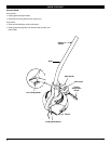
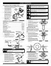
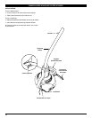
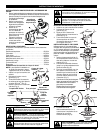
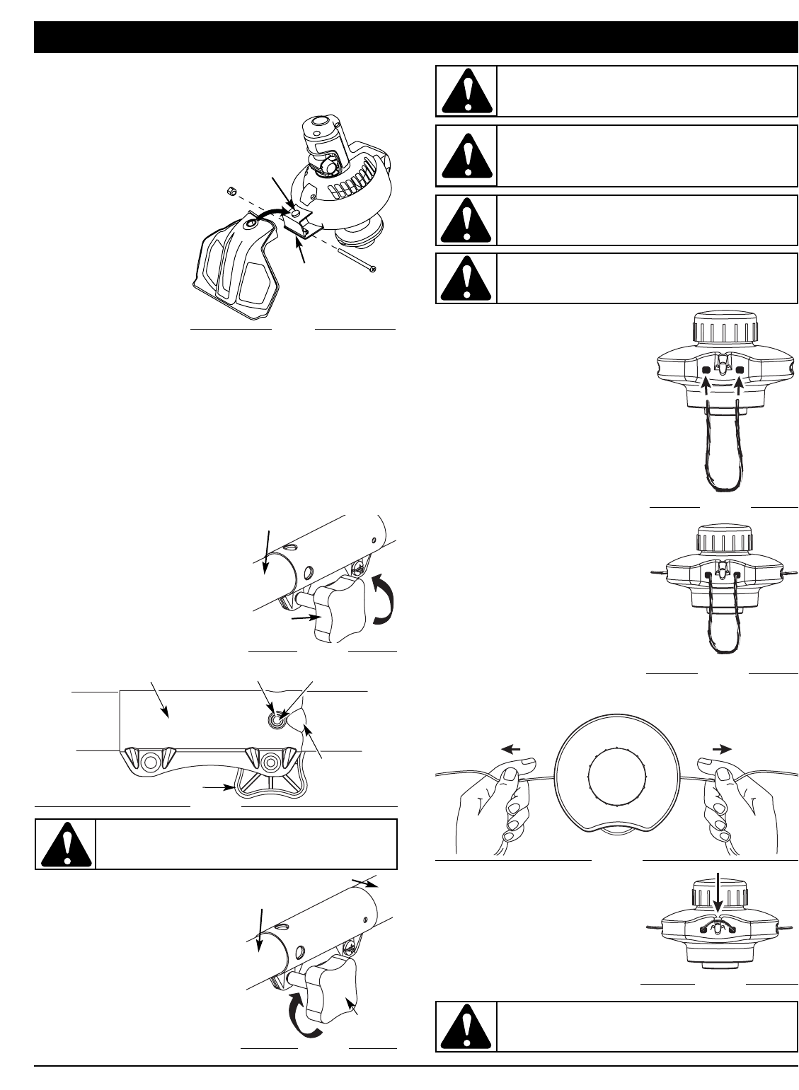
INSTALLING CUTTING ATTACHMENT SHIELD
1. Place the narrow end of the cutting attachment shield over the
shield bracket and position it so that the circular cut-out slips
over the guard assembly peg (Fig. 1).
2. Place the locking nut
into the hexagonal hole
on the left side of the
guard and hold in place.
3. Insert the assembly
screw into the hole on
the right side of the
guard and screw it
into the nut on the left
side using a Phillips-
head screwdriver.
4. Make sure the screw
is tight before
operating the unit.
Fig. 1
Guard
Assembly
Peg
Shield
Bracket
ASSEMBLY INSTRUCTIONS
ASSEMBLING THE COUPLER
The TrimmerPlus® system enables the use of these optional
attachments.
Blower/Vacuum . . . . . . . . . . . . . . . . . . . . . . . . . . . . . . . BV720r
Cultivator . . . . . . . . . . . . . . . . . . . . . . . . . . . . . . . . . . . . GC720r
Hedge Trimmer . . . . . . . . . . . . . . . . . . . . . . . . . . . . . . . HS720r
Lawn Edger . . . . . . . . . . . . . . . . . . . . . . . . . . . . . . . . . . .LE720r
Straight Shaft Trimmer . . . . . . . . . . . . . . . . . . . . . . . . . . SS725r
Snow Thrower . . . . . . . . . . . . . . . . . . . . . . . . . . . . . . . . . ST720r
Turbo Blower . . . . . . . . . . . . . . . . . . . . . . . . . . . . . . . . . TB720r
Tree Pruner . . . . . . . . . . . . . . . . . . . . . . . . . . . . . . . . . . .TP720r
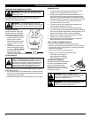
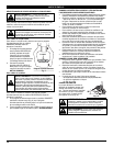
To Install Attachments
NOTE: To make installation easier,
place the unit on the ground or
on a workbench.
1. Make sure the unit is turned
completely off.
2. Turn the knob counterclockwise
to loosen the coupler (Fig. 2).
Knob
Coupler
Fig. 2
Fig. 3
EZ-Link™ Coupler
Release Button
Guide
Recess
Knob
Primary Hole
CAUTION: Lock the release button in the primary
hole (Fig. 3) and securely tighten the knob before
operating this unit.
Attachment
3. While firmly holding the
attachment, push it straight into
the coupler until the release
button (Fig. 3) snaps into the
primary hole (Fig. 3). The
primary hole is on the opposite
side of the coupler from the
knob (Fig. 3). Align the release
button with the Guide Recess
(Fig. 3) to help installation.
4. Turn the knob clockwise to
tighten (Fig. 4).
CAUTION: These attachments are to be snapped
into the primary hole only. Using the wrong hole could
lead to personal injury or damage to the unit.
CAUTION: Before operating this unit, be sure
that the release button is fully snapped into the
primary hole (Fig. 3), and that the knob (Fig. 4) is
securely tightened.
Fig. 4
Knob
Attachment
Upper Shaft Boom
Coupler
WARNING: Never use metal-reinforced line, wire,
chain, or rope. These can break off and become
dangerous projectiles.
WARNING: Always use the correct line length
when installing trimming line on the unit.
To Remove Attachments
1. Make sure the unit is turned
completely off.
2. Turn the knob counterclockwise
to loosen the coupler (Fig. 2).
3. Press and hold the release
button (Fig. 3).
4. While firmly holding the upper
shaft boom (Fig. 4), pull the
attachment out of the coupler.
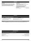
INSTALLING FIXED LINE
Always use 17.5 inches of precut .105”
TrimmerPlus
®
spiral line or 17.5 inches
of .110” trimming line. Lines other than
these may make the unit overheat or
fail.
To install the trimming line:
1. Insert each end of the replace-
ment line into the holes on either
side of retention hook (Fig. 5).
2. Push the ends through until
they stick out of the sides of the
head (Fig. 6).
3. Pull the ends through making
sure that the ends are of equal
length and the middle of the line
is centered between the insertion
holes (Fig. 7).
4. If the ends are not of equal
length, push the longer end back
through the head part way and
pull the shorter end to
compensate. Repeat until both
ends are the same length.
5. Push the trimmer line behind the
hook to secure it from coming
loose while running (Fig. 8).
Fig. 5
Fig. 7
Fig. 6
Fig. 8
WARNING: To avoid serious personal injury,
always turn your unit off before you clean or
service it.