


22
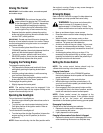
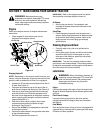
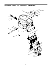
Figure 17
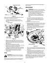
Adjust the drive pedal after replacing the drive belts on
your tractor, if necessary, as follows:
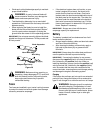
• Locate the speed control assembly on the
underside of the steering support bracket. See
Figure 18.
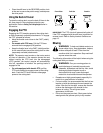
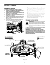
Figure 18
• Remove both hairpin clips from the pin which is
fastened to the speed control assembly (be careful
not to lose the small flat washers found on the pin).
See Figure 18.
• Remove the drive pedal return spring.
• Using two 9/16" wrenches, remove the pin from the
speed control assembly. See Figure 18.
• Thread the idler adjustment rod inward or outward
to lengthen or shorten the travel of the double-idler
bracket until proper adjustment is achieved.
• Reassemble by following the above steps in
reverse order.
Tires
Refer to the tire sidewall for exact tire manufacturer’s
recommended or maximum psi. Do not overinflate.
Uneven tire pressure could cause the cutting deck to
mow unevenly.
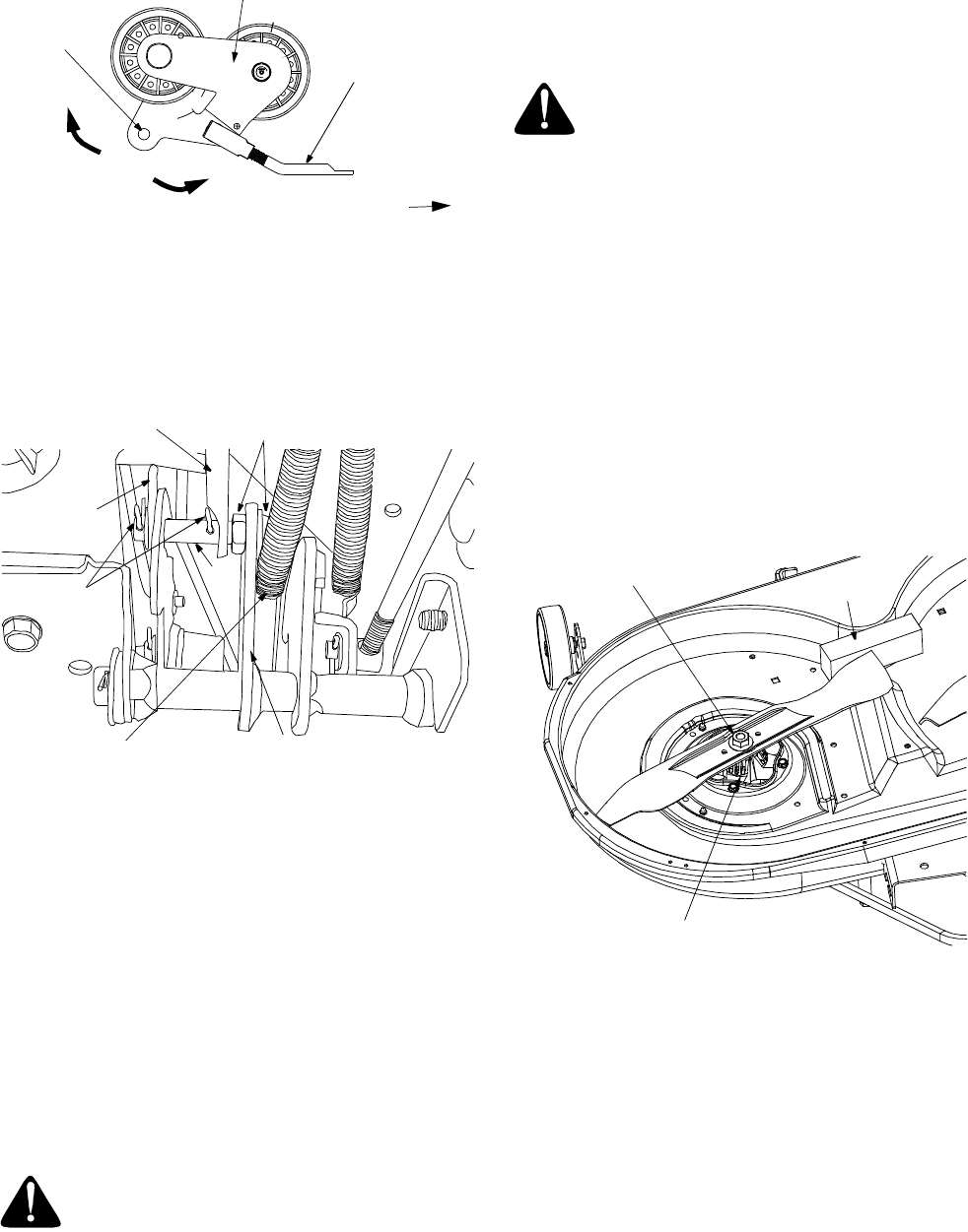
Cutting Blades
• Periodically inspect the blade adapter and/or
spindle for cracks or damage, especially if you
strike a foreign object. Replace immediately if
damaged
.
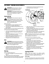
The blades may be removed as follows:
• Remove the deck from beneath the tractor, (refer to
Cutting Deck Removal on page 19) then gently flip the
deck over to expose its underside.
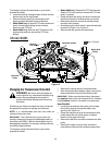
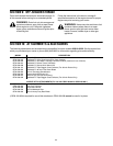
• Place a block of wood between the center deck
housing baffle and the cutting blade to act as a
stabilizer. See Figure 19.
Figure 19
• Use a 15/16" wrench to remove the hex flange nut
that secures the blade to the spindle assembly. See
Figure 19.
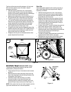
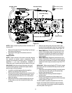
• To properly sharpen the cutting blades, remove
equal amounts of metal from both ends of the
blades along the cutting edges, parallel to the
trailing edge, at a 25° to 30° angle. See Figure 20.
IMPORTANT:
If the cutting edge of the blade has already
been sharpened to within 5/8" of the wind wing radius,
or if any metal separation is present, replace the
blades. See Figure 20.
WARNING:
Never exceed the maximum
inflation pressure shown on the tire sidewall.
Front of Tractor
NOTE:
View shown from above tractor.
Double-idler Bracket
Idler
Adjuster Rod
Hole
1
-
3
/
8
”
Speed Control
Assembly
Hairpin
Clips
Idler Adj. Rod
Pin
Drive Pedal
Return Spring
Place wrenches here
Neutral
Return
Bracket
WARNING:
Be sure to shut the engine off,
remove ignition key, disconnect the spark plug
wire(s) and ground against the engine to
prevent unintended starting before removing
the cutting blade(s) for sharpening or
replacement. Protect your hands by using
heavy gloves or a rag to grasp the cutting
blade.
Spindle Assembly
Hex Flange Nut
Wood Block