


15
5
2. With the drive control released, there must be 1/8”
clearance between the friction wheel and the drive
pulley in all positions of the shift lever.
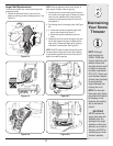
3. With the drive control engaged, the friction wheel must
contact the drive pulley. See Figure 6-8.
4. If adjustment is necessary, loosen the lower hex nut
on the drive cable index bracket and pivot the bracket
upward or downward as necessary. Refer to Figure
5-3. Tighten the lower hex nut to secure the bracket
when correct adjustment is reached.
5. Reassemble the frame cover and return the unit back
to its operating position.
NOTE: If you placed plastic under the gas cap, be certain
to remove it now.
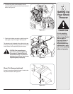
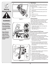
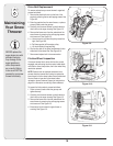
Skid Shoes
The space between this shave plate and the ground can
be adjusted. For close snow removal, place skid shoes in
the low position. Use middle or high position when area to
be cleared is uneven.
1. Adjust skid shoes by loosening the four lock nuts
and carriage bolts and moving skid shoes to desired
position. See Figure 5-4 or 5-5.
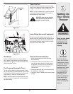
2. Make certain the entire bottom surface of skid shoes
are against the ground to avoid uneven wear on the
skid shoes.
3. Tighten nuts and bolts securely.
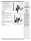
NOTE: Some models are equipped with heavy duty skid
shoes and may be turned over to increase their lifespan.
See Figure 5-5. If shoes are turned they must also
change sides to ensure the “A” on the shoe is towards the
front of the unit.
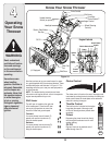
Auger Control
To adjust the auger control, refer to page 13.
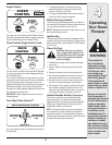
Making
Adjustments
IMPORTAN T
It is not recommended
that you operate this
snow thrower on gravel
as loose gravel can be
easily picked up and
thrown by the auger
causing personal injury
or damage to the snow
thrower.
If for some reason,
you have to operate
the snow thrower on
gravel, keep the skid
shoe in the highest
position for maximum
clearance between the
ground and the shave
plate.
Figure 5-4 - Standard Skid Shoe
Figure 5-5 - Reversible Skid Shoe