


11
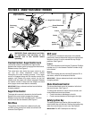
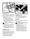
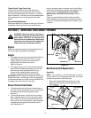
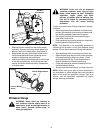
Shift Rod Adjustment
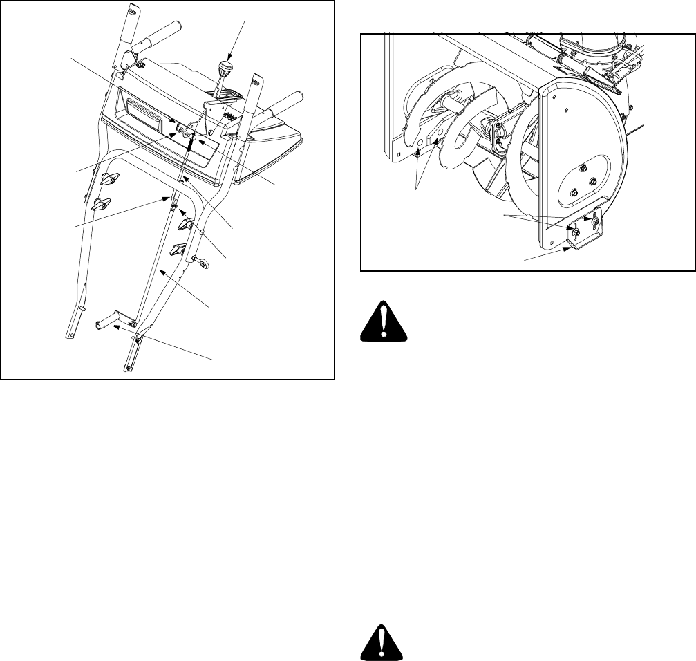
To adjust the shift rod, proceed as follows:
• Remove the hairpin clip and slide the shift rod
connector up, to separate the upper shift rod from
the lower shift rod. See Figure 10.
Figure 10
• Place the shift lever into the sixth (6) position.
• Rotate the shift arm clockwise (from the operator’s
position) as far as it will go.
• Thread the upper shift rod downward until the
elbow on its lower end aligns with the hole found in
the lower shift rod.
• Reconnect the upper shift rod to the lower shift rod
by reinserting the hairpin clip removed earlier and
sliding the shift rod connector back down into place.
IMPORTANT:
Make certain to check for correct
adjustment of the shift rod as instructed under Final
Adjustments in the Assembly Section, before operating
the snow thrower.
Chute Assembly
The distance snow is thrown can be adjusted by
changing the angle of the chute assembly. To do so,
stop the engine by removing the ignition key and loosen
the plastic wing knobs found on either side of the
discharge chute. Pivot the chute upward or downward
before re-tightening the wing knobs.
Auger Control
Refer to Auger Control Test in the Operating Section to
adjust the auger control.
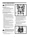
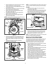
Skid Shoes
The space between the shave plate and the ground can
be adjusted. See Figure 11.
• For close snow removal on a smooth surface, raise
skid shoes higher on the auger housing.
• Use a middle or lower position when the area to be
cleared is uneven.
Figure 11
WARNING: Do not operate this snow
thrower on gravel as loose gravel can be
easily picked up and thrown by the auger
causing injury to the operator and/or
damage to the snow thrower.
• Adjust skid shoes by loosening the four hex nuts
and carriage bolts. Move skid shoes to desired
position.
• Make certain the entire bottom surface of skid shoe
is against the ground to avoid uneven wear on the
skid shoes. Retighten nuts and bolts securely.
Carburetor
• Minor carburetor adjustment may be required to
compensate for differences in fuel, temperature,
altitude and load.
• Refer to the separate engine manual, packed with
your unit, for carburetor adjustment information.
WARNING: If any adjustments need to be
made to the engine while the engine is
running (e.g. carburetor), keep clear of all
moving parts. Be careful of muffler, engine
and other surrounding heated surfaces.
Drive Wheels
• The wheels may be adjusted for two different
methods of operation. Follow the steps below for
adjustment. See Figure 12.
One Wheel Driving
• On the right side of the unit, place klick pin in the
outside axle hole only. Do not place pin through
Shift Lever
Ferrule
Shift Arm
Hairpin
Clip
Lower Shift Rod
Clutch Rod
Upper Shift Rod
Connector
Hairpin Clip
Flat Washer
Skid
Shoes
Carriage
Bolts
Hex Nuts