9/23/2005
Log Splitter Wedge Shim
ITEM
NO.
PART
NUMBER
QTY DESCRIPTION
1 681-04052 1 SHIM ASSEMBLY
2 710-1806 1 SCREW: HHCS: 1/2”-13 x 3.25: GR5
3 712-3022 1 NUT: LOCK: 1/2”-13
4 769-02077 1 THIS INSTRUCTION SHEET
2004 and 2005 Model Year Log
Splitters built between May 1,
2004 and September 15, 2005.
753-05193
PURPOSE:
This service kit provides a shim (spacer) to reduce the gap between the end of the cylinder ram and the back of the
wedge. Perform the Pre-service Inspection to determine if this kit is required or not.
Service Kit 753-05193 Pg 1 of 2 Form No. 769-02077
Models
Affected:
Subject:
Date:
Service Kit
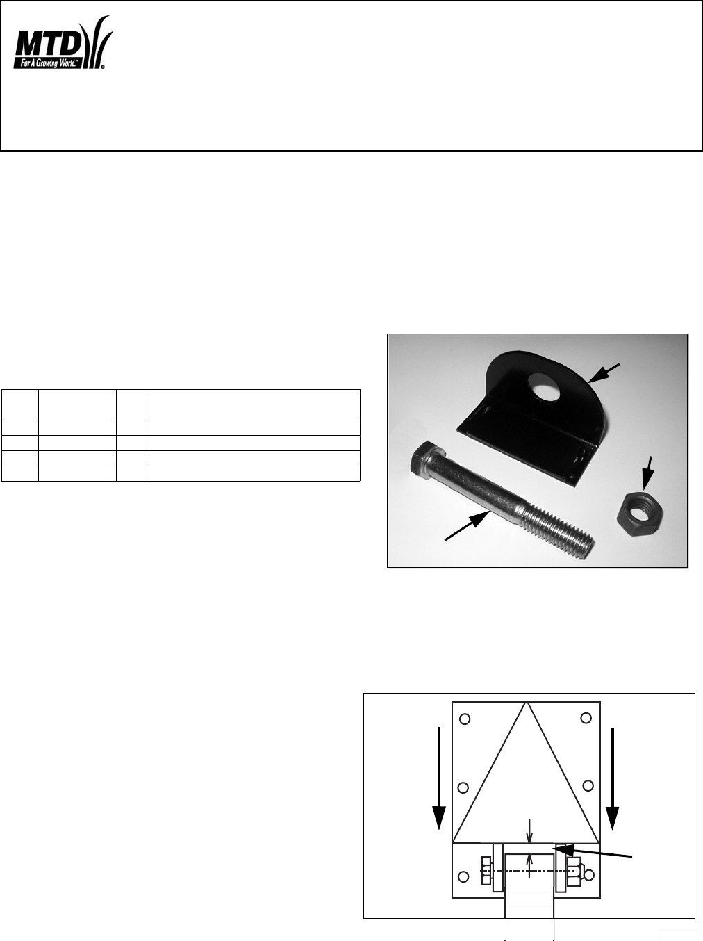
FIGURE 1
1
2
3
.
If the gage
does not go
in the gap, the gap is cor-
rect and this kit is not required. Stop here.
If the gage goes into the gap, the shim provided
should be installed. Proceed to Step 9.
.035"
max.
FIGURE 2
GAP
PUSH
Wedge
Back
NOTE: These materials are prepared for use by trained technicians who are experienced in the service and repair
of equipment of the kind described in this publication, and are not intended for use by untrained or inexperienced
individuals. Such individuals should seek the assistance of an authorized service technician or dealer.
NOTE: Save this Instruction Sheet. Refer to it when ordering replacement parts.
Service Kit Contents
(See Figure 1)
Pre-service Inspection:
These instructions are written with the assumption that
the unit has been in service already or is being prepared
for delivery.
1. To determine if this service kit is required the follow-
ing check must be made.
2. Place beam in the horizontal position and lock in
place.
3. Check engine oil level and hydraulic fluid level.
4. Start engine and extend ram so the splitting wedge is
about 4”- 8” from beam’s foot. Turn off engine.
5. Release pressure in the system by shuttling the direc-
tion control lever from the forward to the retract positions
several times.
6.Using two 3/4” wrenches loosen the cylinder to wedge
mounting bolt to relax the wedge.
7. With wood blocking braced against the beam’s foot,
push the wedge back toward the cylinder’s ram end and
secure in this position.
8. Using a.035” feeler gage, try to insert the gage
between the end of the ram and the back side of the
wedge pocket. See Figure 2.
Read through and understand these instructions completely before proceeding with repair.


