


21
4. Balance the deck by using a wrench to turn the
adjustment gear (found immediately behind the hex
cap bolt just loosened) clockwise/up or counterclock-
wise/down. The deck is properly balanced when both
blade tip measurements taken earlier are equal.
5. Retighten the hex cap bolt on the left deck hanger
bracket when proper adjustment is achieved.
Parking Brake Adjustment
WARNING: Never attempt to adjust
the brakes while the engine is run-
ning. Always disengage PTO, move
shift lever into neutral position, stop
engine and remove key to prevent
unintended starting.
IIf the tractor does not come to a complete stop when the
brake pedal is completely depressed, or if the tractor’s
rear wheels can roll with the parking brake applied, the
brake is in need of adjustment. See an authorized Service
Dealer to have your brakes properly adjusted.
Seat Adjustment
Quick Adjust Seat (If so equipped)
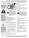
WARNING: Before operating this
machine, make sure the seat is
engaged in the seat stop, stand
behind the machine and pull back
on seat until fully engaged into stop.
• To adjust the position of the seat on models equipped
with a seat adjustment lever, move the lever to the left
and slide the seat forward or rearward. Refer to the
Set-Up section. Make sure seat is locked into position
before operating the tractor.
Knob Adjustment Seat (if so equipped)
To adjust the position of the seat on models so equipped,
loosen the two knobs on the bottom of the seat. Refer to
the Set-Up section. Slide the seat forward or backward as
desired. Retighten the two knobs.
Standard Seat (if so equipped)
To adjust the position of the seat, loosen the two hex
screws on the bottom of the seat. Slide the seat forward
or backward as desired. Retighten the two screws. Refer
to the Set-Up section.
5
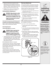
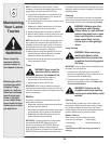
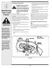
WARNING
Adjusting
Your Lawn
Tractor
Before operating this
machine, make sure
the seat is engaged in
the seat stop, stand
behind the machine
and pull back on seat
until fully engaged into
stop.
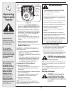
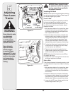
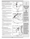
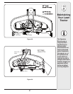
Figure 5-3
NOTE: Threading the
ball joints too far onto
the drag links will cause
the front tires to “toe-in”
too far. Proper toe-in
is between 1/16” and
5/16”.
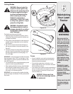
Steering Adjustment
If the tractor turns tighter in one direction than the other,
or if the ball joints are being replaced due to damage or
wear, the steering drag links may need to be adjusted.
Adjust the drag links so that equal lengths are threaded
into the ball joint on the left and right side:
1. Loosen the jam nut found on the drag link at the rear
of the ball joint. See Fig. 5-3.
2. Remove hex nut on the top of ball joint. See Fig. 5-3.
3. Thread the ball joint toward the jam nut to shorten
the drag link. Thread the ball joint away from the jam
nut to lengthen the drag link.
4. Replace hex nut and retighten the jam nut after
proper adjustment is achieved.
NOTE: Threading the ball joints too far onto the drag
links will cause the front tires to “toe-in” too far. Proper
toe-in is between 1/16” and 5/16”.
Front tire toe-in can be measured as follows:
1. Place the steering wheel in position for straight
ahead travel.
2. In front of the axle, measure the distance horizontally
from the inside of the left rim to the inside of the right
rim. Note the distance.
3. Behind the axle, measure the distance horizontally
from the inside of the left rim to the inside of the right
rim. Note the distance.
4. The measurement taken in front of the axle should
be between 1/16” and 5/16” less than the measure-
ment taken behind the axle. Adjust if necessary.
Drag Link
Hex Nut
Jam
Nut
Ball
Joint