


8
ASSEMBLY INSTRUCTIONS
Screw
and Nut
Screw and Nut
Self Tapping
Screw
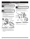
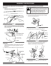
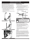
ATTACHING AND REMOVING THE
BLOWER/VACUUM TUBE
Attaching
NOTE: The
blower/vacuum tube comes unassembled
on this unit. Installation is required to provide
safe and easy use for the operator.
1. Remove the screws and nuts provided from the
hardware pack.
2. Insert the blower/vacuum tube all the way into the
opening on the motor housing until the holes in the
tabs on the blower/vacuum tube align with the screw
holes in the housing (Fig. 1).
3. Insert the 2 (two) 8-32 x 3/4” slotted T20 Torx screws
into the right side of the motor housing and the 2 (two)
nuts into the left side of the motor housing (Fig. 1).
Fig. 1
4. Tighten the screws firmly. Do not over-tighten.
5. Install the 2 (two) remaining self-tapping 8-16 x 3/4”
slotted T20 Torx screws into the holes on either side
of the housing (Fig. 1). Tighten until snug, but do not
over-tighten.
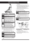
Removing
NOTE: It may be necessary to remove the
blower/vacuum tube to clear a blocked tube or
impeller.
1. Remove the 2 (two) self-tapping screws from either
side of the housing.
2. Remove the 2 (two) screws and nuts holding the
blower/vacuum tube on the housing (Fig. 2).
NOTE: Keep the hardware in a safe place for future use.
Fig. 2
3. Remove the blower/vacuum tube from the motor
housing.
4. Replace the
blower/vacuum tube before use.
Screw
Nut
Blower/Vacuum
Tube
Motor Housing
Self-Tapping Screw
WARNING: To prevent serious personal
injury, stop the engine, disconnect the spark
plug wire and allow the impeller to stop
before attaching or removing tubes.
WARNING: To prevent serious personal
injury, stop the engine and allow the impeller
to stop before attaching or removing tubes.
WARNING: To avoid serious personal injury,
the blower/vacuum tube and vacuum bag
must be used when operating this unit.