


8
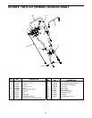
SECTION 5: MAKING ADJUSTMENTS
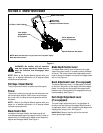
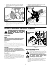
Bevel Adjustment (models so equipped)
NOTE: Edger features vary by model. All edger models
do NOT come equipped for blade tilt adjustment nor is
there a blade tilt kit available to modify your edger if it
was not purchased equipped to do so.
The angle of the edger blade can be adjusted by
placing the bevel adjustment lever in one of three
positions for edging/trenching or beveled edging. See
Figure 5.
Figure 5
WARNING: Rotating cutting blade may
throw objects causing personal injury.
Keep area clear of bystanders and do not
operate without guards in place.
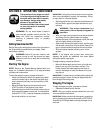
Beveling
Set the bevel adjustment lever (refer to Figure 5) in the
first (left hand) or third (right hand) notch to place the
edger blade in position for beveling. See Figure 6.
Figure 6
Edging
Set the bevel adjustment lever (refer to Figure 5) in the
center notch to place the edger blade in a 90° position
for edging. See Figure 7.
Figure 7
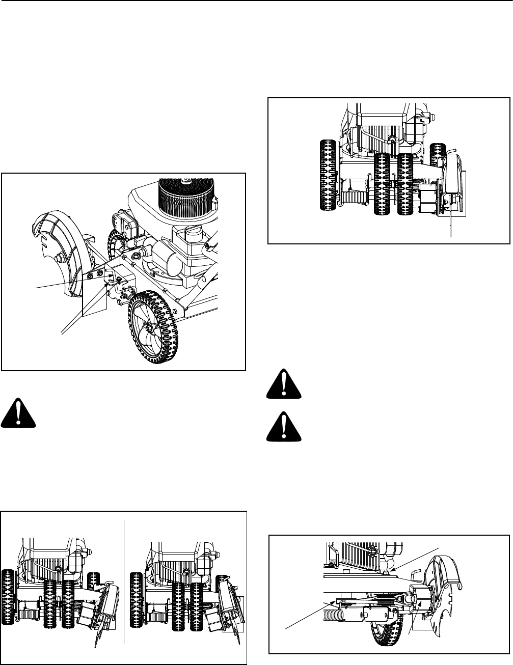
Trenching (models so equipped)
NOTE: Edger features vary by model. All edger models
do NOT come equipped for trenching. If your edger was
not purchased equipped to do so, you may purchase
part no. 736-04088 (flat washer) and part no. 781-0748
(triplex edger blade) to utilize this feature.
WARNING: Disconnect the spark plug wire
and ground against the engine before
performing the following steps.
WARNING: The edger blade is sharp. Wear
leather work gloves to protect your hands
when working around the edger blade.
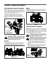
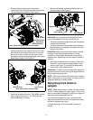
• Working in front of the edger, loosen the flange lock
nut on top of frame, allowing the idler pulley
assembly to pivot slightly out from the frame. See
Figure 8.
• With your other hand, carefully reach under the rear
of the unit and remove the belt from around the
engine flywheel pulley. See Figure 8.
Figure 8
Bevel
Adjustment
Lever
Beveling
Edging/Trenching
Position Shown
Beveling Positions
Edging/Trenching Position
Engine
Flywheel Pulley
Spindle
Sheaves Belt Guard
Flange Lock Nut