10
6
Maintaining
& Servicing
Your Edger
WARNING
Disconnect the spark
plug wire and ground
against the engine
before performing
any adjustment,
repairs or mainte-
nance.
The edger blade
is sharp. Wear
leather work gloves
to protect your hands
when working around
the edger blade.
Disconnect the spark
plug wire and ground
against engine
before performing the
following steps.
WARNING: Disconnect the spark plug
wire and ground against the engine
before performing any adjustment,
repairs or maintenance.
Lubrication
Engine
Refer to the Engine Manual packed with your edger for a detailed
description of all engine-related service specifications.
Wheels
Lubricate the wheels and bearings at least once a season
with a light oil. Also if the wheels are removed for any
reason, lubricate the surface of the axle bolt and the inner
surface of the wheel with light oil.
Pivot Points
Lubricate the pivot points on the blade control bail, blade
depth control lever, and if applicable, the blade adjustment
lever, and curb height adjustment lever with light oil at
least once a season.
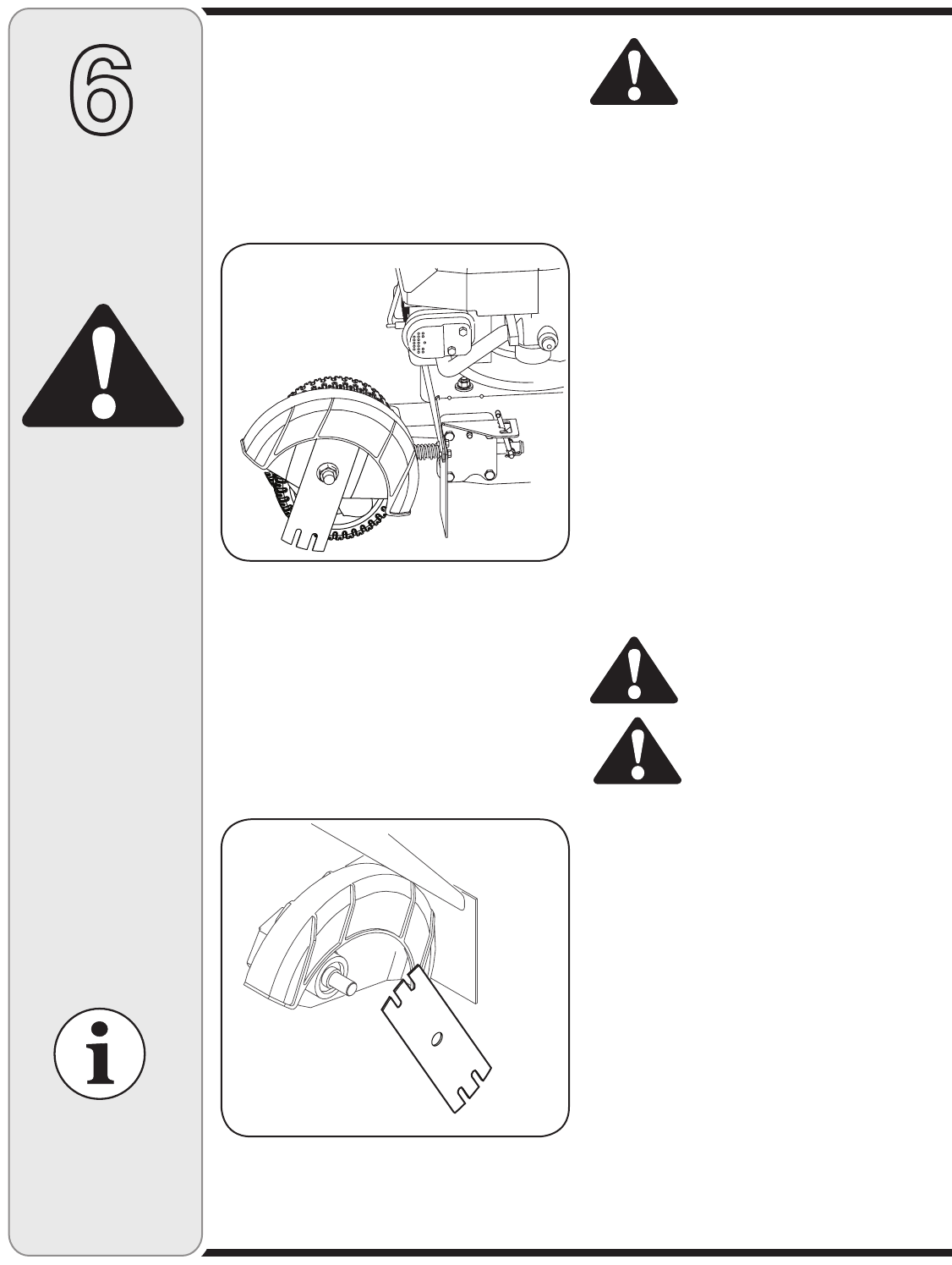
Bearing Block
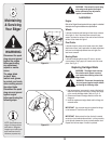
Lubricate the bearing block every 25 hours or at least
once a season. Simply apply oil at each end of the cover
plate. See Fig. 6–1.
Replacing the Edger Blade
WARNING: The edger blade is sharp.
Wear leather work gloves to protect
your hands when working around the
edger blade.
WARNING: Disconnect the spark plug
wire and ground against engine before
performing the following steps.
1. Use two wrenches (one wrench to prevent the hex bolt
head from spinning and the other to remove the flange
nut) to remove the edger blade. Refer to Fig. 6–2.
2. Remove and discard the edger blade but retain the
flange nut.
3. Install the replacement edger blade and the flange nut
removed earlier.
IMPORTANT: Use a torque wrench to tighten the flange
nut to between 37 foot-lbs. and 50 foot-lbs.
IMPORTANT: Make certain that the drive belt is seated
correctly on the blade spindle and that it is riding smoothly
on the spindle sheaves and is not pinched between them.
Repeat the first three steps if the belt is pinched.
Figure 6–1
NOTE: Specifications are
subject to change without
notification or obligation.
Images my not reflect your
exact model and are for
reference purposes only.
Figure 6–2


