


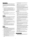
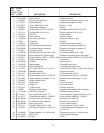
7
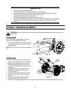
Starter Rope
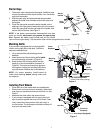
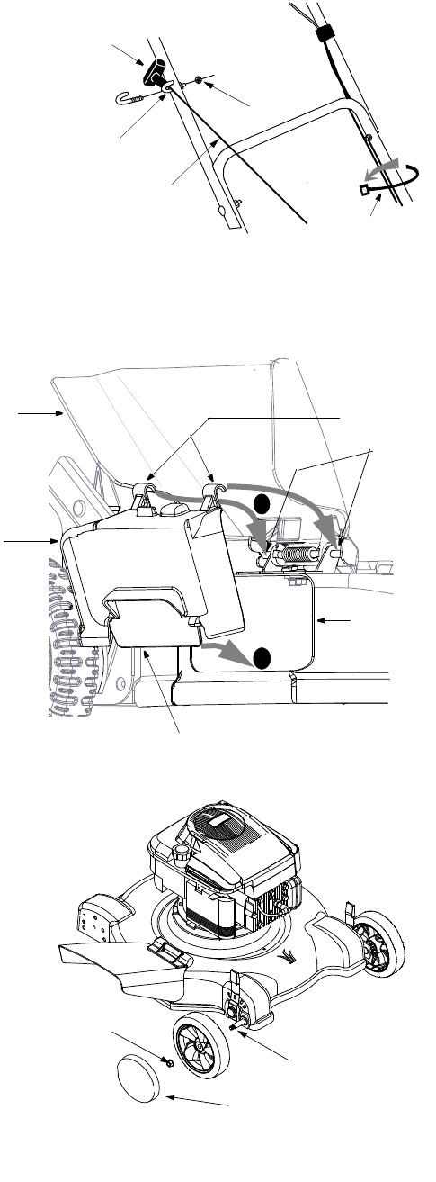
1. The starter rope is attached to the engine. Additional rope
may be wound around the starter handle. If so, unwind the
rope from the handle.
2. With the spark plug wire disconnected and grounded,
depress the blade control handle and pull the rope out of
the engine.
3. Place the rope guide around the starter handle, so the
opening in the rope guide is toward the front of the mower.
Insert the rope guide into the right side of the handle, and
secure with hex locknut. See Figure 5.
NOTE: If the starter rope becomes disconnected from rope
guide on handle, disconnect and ground the spark plug
wire. Depress the blade control handle and pull the starter
rope out from engine slowly. Slip the starter rope into the rope guide bolt on handle.
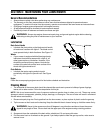
Mulching Baffle
If your mower is equipped with a mulching baffle,
install it on the right side of the deck. Follow the
sequence indicated here.
1. Lift up and hold the side-discharge chute
deflector.
2. Insert bottom lip of the mulching baffle inside
the chute opening (marked 1 in Figure 6).
3. Snap hooks of the mulching baffle over the
hinge pin of the chute deflector (marked 2 in
Figure 6). The hooks must snap into place on
the hinge pin, locking the mulching baffle firmly
onto the mower. Release the chute deflector.
NOTE: For proper assembly, install bottom lip
inside chute opening before placing hooks over
the hinge pin.
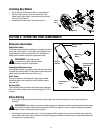
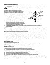
Installing Front Wheels
• Place the front of the mower deck on raised blocks.
• Remove lock nut from pivot arm assembly, slide wheel
onto pivot arm assembly and secure with lock nut. See
Figure 7.
• Assemble the other side in the same manner.
• If your mower is equipped with hub caps, place hub
caps in position against the inner hub of wheel. Press
firmly around the center portion of the hub cap in a
circular motion. The hub caps are flexible and they will
snap over the wheel hubs.
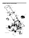
Figure 5
Cable
Tie
Hex
Lock
Nut
Rope
Guide
Starter
Handle
Starter
Rope
Chute
Deflector
Chute
Lip of Mulching Baffle
Hooks
Mulching
Baffle
(insert inside chute opening)
Opening
Figure 6
1
2
H
i
n
g
e
P
i
n
Lock Nut
Pivot Arm
Assembly
Hub Cap (If Equipped)
Figure 7