


8
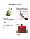
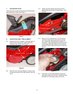
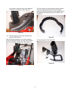
NOTE: During reassembly, align the chute
assembly by facing it towards the plastic retain-
ing ring. Be sure the chute is positioned all the
way to the right or left upon re-assembly. See
Figure 27.
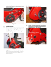
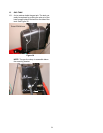
Check that the upper and lower flanges lock into the
retaining ring and that the latch closes and locks prop-
erly. See Figure 28.
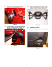
12. ENGINE REMOVAL
12.1. Remove the discharge chute and engine cowl-
ing.
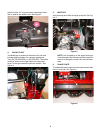
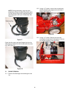
12.2. Using a 1/2” socket, remove the four bolts and
spacers attaching the engine to the left side of
frame. See Figure 29.
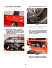
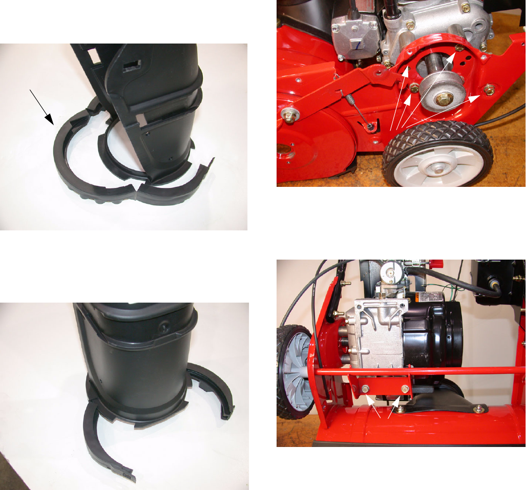
12.3. Using a 1/2” socket, Remove the two bolts
securing the lower base of the engine to the sup-
port bracket welded to the wheel axle.
Figure 27
Retaining Ring
Figure 28
Figure 29
Engine Mounting Bolts (4)
Lower Engine Mounting Bolts