


7
If the spiral on the chute directional control cannnot be
adjusted properly, follow the steps below:
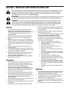
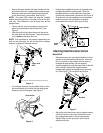
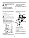
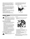
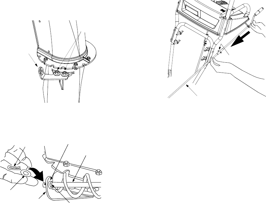
• Loosen the two hex nuts which secure the chute
directional control support bracket (see Figure 8) to
the snow thrower housing, beside the discharge
chute.
Figure 8
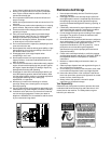
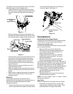
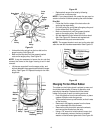
• Remove the hairpin clip and one flat washer from
the lower end of the chute directional control. Leave
the other flat washer in place on the end of the rod.
Figure 9
• Insert the lower end of the chute directional control
into the hole in the plastic bushing in the chute
directional control support bracket. See Figure 8.
• Place the other flat washer onto the end of the
chute directional control, and secure with hairpin
clip. See Figure 9.
• Tighten the nuts on the chute directional control
support bracket securely.
• Adjust the eyebolt on the chute directional control
so the chute directional control does not touch the
engine.
• Move the hex nut against the handle (if necessary).
• Tighten wing nut with eye bolt to secure chute
directional control.
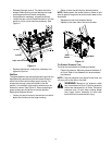
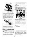
Model 663H
For packaging purposes, the two-piece chute
directional control was attached to the snow thrower on
the two ends, but was kept loose at the middle.
Assemble as follows:
• Remove the hairpin clip from the chute directional
control. Align holes on the upper and lower pieces
of the chute directional control, and insert the
hairpin clip again. See Figure 10.
Figure 10
Final Adjustments
Chute Directional Control Support Bracket
To adjust the chute directional control support bracket,
refer to Figure 8 and accompanying instructions.
Traction Control and Shift Lever
To check the adjustment of the traction control and shift
lever, proceed as follows:
• Move the shift lever into sixth (6) position.
• With traction control released, gently push the
snow thrower forward, then pull it back. The
machine should move freely.
• Engage traction control, and try to move the
machine both forward and back. You should
experience resistance.
• Move the shift lever into the fast reverse (R2)
position and repeat the previous two steps.
If you experienced resistance either when repositioning
the shift lever from 6 to R2 or when attempting to move
the machine with the traction control released, you
should NOT operate the snow thrower before adjusting
the traction control. To adjust, proceed as follows:
• Loosen the jam nut on the traction control cable
and UNTHREAD the cable one full turn.
• Recheck adjustment.
• Retighten the jam nut to secure the cable when
correct adjustment is reached.
NOTE: For more details, refer to Traction Control
Adjustment on page 12.
Auger Control
Check the adjustment of the auger control as follows:
• Push down on the auger control until the small
rubber bumper contacts the upper handle. There
should be slack in the auger control cable.
Carriage Bolts
Hex Lock Nuts
Chute Directional
Control
Support Bracket
Chute Crank
Plastic Bushing
Lower Chute
Crank Bracket
Hairpin Clip
Flat Washer
Flat Washer
Chute Directional
Control
Hairpin Clip