


9
• After clearing snow, allow the engine to run for an
extra few minutes before storing to help dry any
moisture on the engine.
• To stop the engine: Turn the ignition key
counterclockwise to the OFF position. Refer to
Ignition Key on page 7. Remove the key form the
snow thrower’s ignition switch before storing.
IMPORTANT:
Keep the ignition key in a safe place. The
engine can not be started without it.
• Wipe all the snow and any moisture which has
formed, from the unit.
• Move the choke lever back and forth several times.
SECTION 5: MAKING ADJUSTMENTS
WARNING: NEVER attempt to make any
adjustments while the engine is running, except
where specified in the operator’s manual.
Control Cable & Belt Tension
As a result of both the control cable and the drive belt
stretching due to wear, periodic adjustments may be
necessary.
If the auger seems to hesitate when rotating while the
engine maintains a constant speed, an adjustment is
necessary. Proceed as follows:
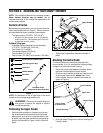
The upper hole in the control handle provides for an
adjustment in cable tension. To adjust, disconnect the
end of control cable from the bottom hole in the control
handle and reinsert it in the upper hole. Refer to Figure
3 . Test the snow thrower to see if there is a noticeable
difference.
If additional adjustment is required, proceed as follows.
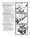
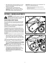
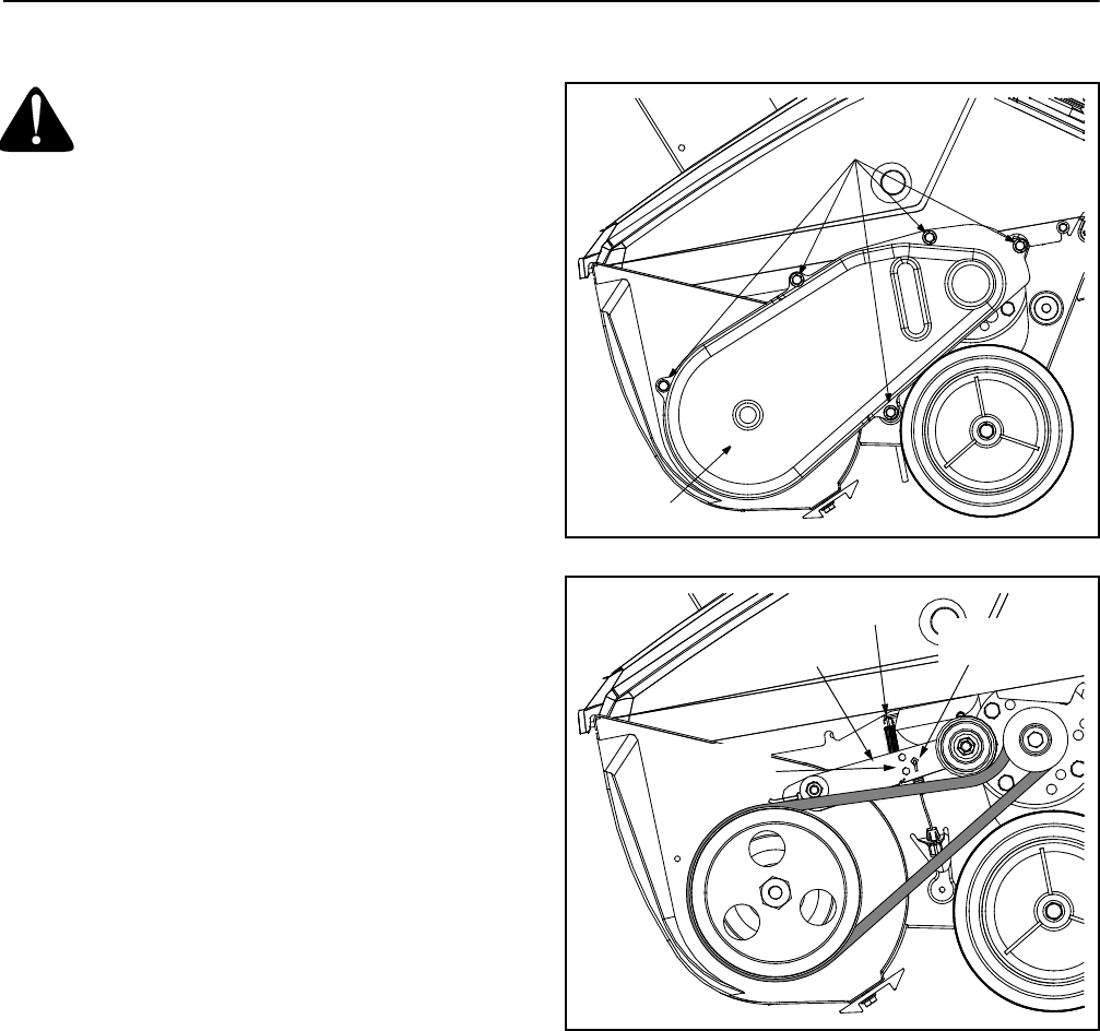
• Remove the belt cover from the left side of the
snow thrower’s auger housing by unthreading the
five hex screws which secure it in place. See Figure
8.
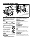
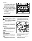
There are three adjustment holes provided in the idler
bracket assembly. To adjust, proceed as follows:
• Move the extension spring (found on the end of the
control cable) from the low position to the middle
position on the idler bracket. See Figure 9.
NOTE: Be careful not to lose the idler spring when
moving the clutch cable spring. See Figure 9.
• If the extension spring is already found in the
middle position on the idler bracket, move it from
the middle position to the high position.
• Reattach the belt cover with the five hex screws
removed earlier.
Figure 8
Figure 9
Hex Screws
Belt Cover
Idler Bracket
Control Cable
Spring
Idler Spring
Adjustment
Holes