


9
NOTE:
If the control handle is disassembled from
the upper handle for any reason, assemble the
control handle by inserting the ends into the holes
on each side of the upper handle. The hole in the
control handle must be on the left side of the upper
handle, and control handle must touch the upper
handle when engaged (squeezed against the upper
handle).
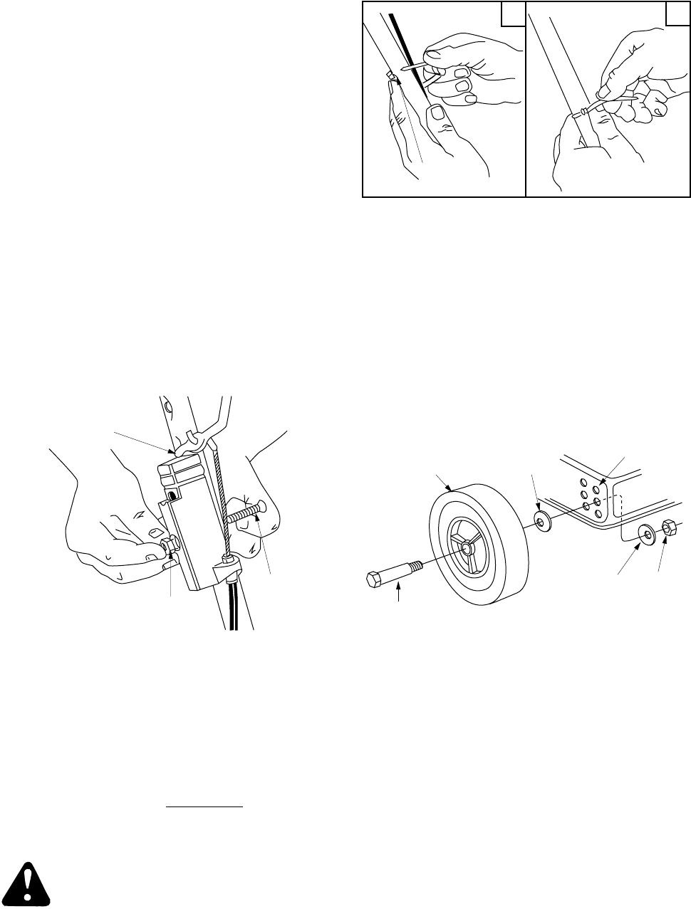
1. Remove the truss machine screw and hex lock
nut from the middle of the control box using a
phillips screwdriver. Place your finger over the
hex lock nut to hold it inside the control box so
you can unscrew the truss machine screw.
2. Make certain the blade control handle is on
top
of the upper handle.
3. Route the control box (with cable attached)
under the lower handle.
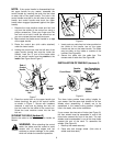
4. Holding the control box near the left side of the
upper handle (control box must be inside the
handle), hook the “Z” end of the brake cable
into the control handle from the
outside
to the
inside
. See Figure 6 and Figure 7.
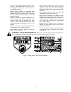
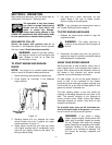
Figure 7
5. Place the control box on the upper handle just
below (touching) the end of the control handle
as shown in Figure 7. Secure with hardware
removed in step one by placing hex lock nut
into the indent on the inside of the control box.
Screw the truss machine screw into the hex
lock nut.
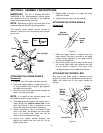
SECURING THE CABLE (Har
dware D)
Secure the cable to the left side of the handle as
follows.
WARNING:
When attaching the control
cable, the cable must be routed to avoid
contact with all sharp edges and hot
surfaces to prevent damage to the cable,
which will render the controls inoperative.
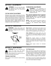
Figure 8
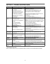
1. Insert posts on cable ties into holes provided on
the inside of the handle, one on the upper
handle and two on the lower handle. The holes
may be either on the inside or outside of the
handles. See Figure 8A.
2. Secure the cable with the cable ties. Trim
excess ends of cable ties. See Figure 8B.
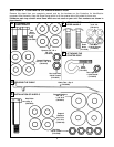
INSTALLATION OF WHEELS
(Hardware E)
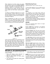
Figure 9
The three holes provide three cutting heights for
your mower. Use the same hole location for all four
wheels when assembling. If wheels are to be
assembled in the lowest cutting position (highest
hole in the deck), refer to the note below.
If your mower has two sets of holes (see Figure 9),
the front wheels must be assembled in one of the
three holes nearest the front of the deck. The rear
wheels must be assembled in one of the three holes
nearest the rear of the deck. To assemble the
wheels: (See Figure 9).
1. Block up the mower securely.
2. Place axle bolt through wheel. (Hub side of
wheel must face deck.)
End of
Handle
Control
Hex Lock
Nut
Truss
Machine
Screw
Cable Tie
Post on
AB
Axle
Bolt
Front Wheel
Smaller
Cupped
Washer
Use These Holes
for Front Wheels
Larger
Cupped
Washer
Hex
Nut