OM-4433 Page 25
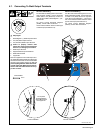
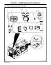
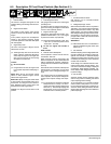
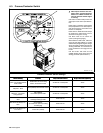
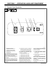
6-2. Description Of Front Panel Controls (See Section 6-1)
Engine Starting Controls
1 Preheat Switch
Use switch to energize starting aid for cold
weather starting (see starting instructions fol-
lowing).
2 Engine Control Switch
Use switch to start engine, select engine
speed (if unit has auto idle option), and stop
engine.
In Run position, engine runs at weld/power
speed. In Auto position (optional), engine
runs at idle speed at no load and weld speed
with load applied.
3 Engine Stop Lever
Use lever to stop engine if Engine Control
switch does not work.
. The Engine Stop lever shuts off the fuel
supply. However, the Engine Stop lever
will not stop the engine if the engine can
draw fuel-rich air from the surrounding
atmosphere (oil refineries).
To Start:
Y Do not use ether.
. If engine does not start, let engine come
to a complete stop before attempting re-
start.
Above 325 F (05 C): turn Engine Control
switch to Start. Release Engine Control
switch when engine starts.
Below 325 F (05 C): turn engine control switch
to Auto position. Push Preheat switch up for
60 seconds. Turn Engine Control switch to
Start. Release Engine Control switch and
Preheat switch when engine starts.
To Stop: turn Engine Control switch to Off
position.
Engine Gauges, Meters, And Lights
4 Fuel Gauge/Hourmeter
Use gauge to check fuel level or total engine
operating hours.
To check fuel level or engine hours when en-
gine is not running, turn Engine Control switch
to Run or Auto (optional) position.
5 Engine Indicator Light
Light goes on and engine stops if engine tem-
perature exceeds 230° F (110° C) or engine
oil pressure is below 10 psi (69 kPa).
. Normal engine temperature is 180 - 2035
F (82 - 955 C). Normal oil pressure is 30
- 60 psi (207 - 414 kPa).
Y Do not run engine until trouble is
fixed.
Weld Controls
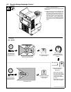
6 Remote Control Receptacle
Use receptacle to connect remote controls,
wire feeders, and tools.
When a remote control is connected to the
Remote receptacle, the Auto Sense Remote
feature automatically switches voltage/am-
perage control to the remote control (see Sec-
tion 5-9).
With remote control connected, weld output is
determined by a combination of front panel
and remote control voltage/amperage set-
tings.
If no remote control is connected to the Re-
mote receptacle, the front panel Voltage/Am-
perage control adjusts voltage and amper-
age.
. If a remote device connected to Remote
Receptacle RC14 is faulty or is discon-
nected, the meters display Help 25 (see
Section 8-11). Clear fault by stopping and
restarting the unit or by turning Process/
Contactor switch to another position.
7 Process/Contactor Switch
See Section 6-3 for Process/Contactor
switch information.
8 Voltage/Amperage Control
With Process/Contactor switch in any Stick or
TIG setting, use control to adjust amperage.
With Process/Contactor switch in any Wire
(MIG) position, use control to adjust voltage.
With Voltage/Amperage Adjust Switch in Re-
mote position, control limits the remote am-
perage in Stick or TIG mode, but has no effect
in Wire (MIG) modes.
Weld Meters
. Weld meters also work in combination to
display troubleshooting help codes (see
Section 8-11).
9 DC Voltmeter
Voltmeter displays preset voltage (MIG weld-
ing) with contactor off, and actual output volt-
age with the contactor on. Voltmeter displays
voltage at the weld output terminals, but not
necessarily the welding arc due to resistance
of cable and connections.
To set voltage, turn contactor off and turn Pro-
cess/Contactor switch to Wire position. Turn
V/A control until desired voltage is displayed
on Voltmeter. When welding is finished, volt-
meter displays weld voltage and then defaults
to preset voltage.
10 DC Ammeter
Ammeter displays preset amperage (Stick
and TIG only) when not welding, and actual
output amperage when welding.
To set amperage, turn Process/Contactor
switch to Stick or TIG position. Turn V/A con-
trol until desired amperage is displayed on
Ammeter. When welding is finished, ammeter
displays weld amperage and then defaults to
preset amperage.


