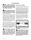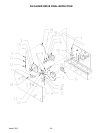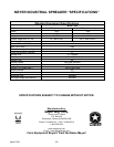
SPINNER MATERIAL GUIDES
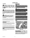
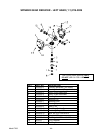
Regularly inspect and adjust two spinner material
guides located at both the left rear and right rear of the
spreader. Create a 1/4-1/2”
clearance between material
guides and spinner teeth, figure 13. Maintain the recom
-
mended clearances for maximum spreading pattern.
Adjust to prevent excessive manure build-up on mate
-
rial guide inner surfaces. Adjust to prevent manure
chunks or foreign object lodging between material
guides and spinner teeth.
NOTE: Excessive lodging can cause premature spinner
tooth wear, “bent-over” or even breakage.
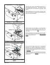
SPRING LOADED MATERIAL GUIDE
ADJUSTMENT
Adjustments for the 1/4-1/2” clearance of each material
guide to spinner tooth is made by tightening or loosen
-
ing the 1” nut on the material guide spring linkage shaft
assembly. Tighten nut to increase clearance and loosen
nut to decrease clearance between the material guides
and spinner teeth. Once recommended clearance is ob
-
tained turn spinners over by hand in the direction by
which the spreader would turn to check clearance. Do
not turn in the opposite direction as front chain tightener
damage could occur.
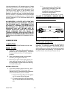
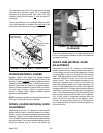
SHEAR ARM MATERIAL GUIDE
ADJUSTMENT
Adjustment for the1/4-1/2” clearance of each material
guide to spinner tooth is made by loosening the jam nut
on the linkage arm and turning the linkage arm to either
move the guide in closer or out farther from the spinner
teeth. After adjustment has been made for the 1/4-1/2”
clearance retighten the jam nut to hold the material
guide in place. Once recommended clearance is ob
-
tained turn spinners over by hand in the direction by
which the spreader would turn to check clearance. Do
not turn in the opposite direction as front chain tightener
damage could occur. If foreign objects enter the spinner
area the front pivot bolt on the shear arm is designed to
shear. The extension spring will pull the material guide
away from the spinner until the shear bolt is replaced.
The ½-13x3” grade 5 replacement machine bolts are
stored on the left side plate for the gearbox mount
channel. For replacement install with ½” flat washer on
top of shear eye and on bottom of block and tighten ny
-
lon locknut firmly.
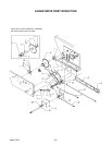
Model 7200 -19-
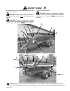
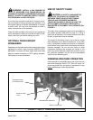
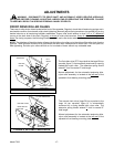
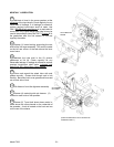
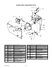
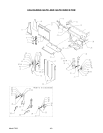
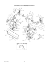
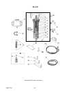
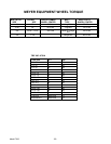
FIGURE 12. SIDE SHAFT CHAIN DRIVE
SIDE LINE SHAFT
DRIVE SPROCKET
PTO INPUT
SPRING LOADED
ADJUSTER
IDLER NYLON
ROLLER
FIGURE 13. MATERIAL GUIDE
CLEARANCE
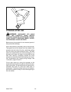
The side shaft chain drive (PTO input shaft to the side
line shaft drive sprocket, figure 12) is automatically
tensioned by a spring loaded idler nylon roller. The
extension spring should extend 2"
from its neutral 5"
total length.
Manual adjustment for the automatic tensioning idler,
nylon roller assembly is located at the right rear
of the
spreader’s front bearing mounting plate.
1/4”-1/2”