12
HYDRAULICS
LEAKING HIGH PRESSURE FLUIDS CAN INJECT THEMSELVES UNDER THE SKIN OF PERSONS
NEAR A LEAK, CREATING GRAVE MEDICAL RISKS. TAKE CARE TO AVOID EXPOSURE TO
HIGH PRESSURE FLUIDS.
1 . Hydraulic components should be kept as clean as possible during assembly operations.
2. Galvanized pipe and pipe fittings must not be used because flaking or galvanizing material can cause
damage to major hydraulic components.
3. A pipe joint sealant, compatible with hydraulic oil, must be applied to all screwed fittings. (Teflon tape is not
recommended.)
4. Hose should be protected where severe wear may be caused by vibration or sliding movement.
5. Long runs of hose should be supported by tie wiring or clamping.
6. Pressure and return hoses, connected to hydraulic motors, may be reversed for proper motor rotation.
Spinner rotates in a clockwise direction when looking down from top.
7. Use hose manufacturer’s recommendations for fitting re-useable hose ends.
8. Hydraulic pumps must be mounted so shaft rotates in direction of arrow.
9. Locate reservoir as close to pump as possible. It may be installed on truck frame or truck box.
10. Hydraulic return line filter is screwed directly onto reservoir with cartridge down. Oil must flow through filter
in direction of arrow on filter.
11. Install the quick connect couplings so that when disconnected, there is a male and female on the truck as
well as on the spreader. This way, hoses will always be hooked up properly. and hose ends can be coupled
together when spreader is in storage to prevent system contamination.
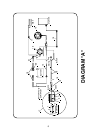
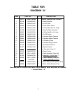
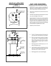
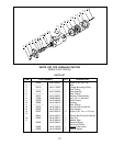
12. See page 13 for valve assembly
13. Operate hydraulic system for several minutes to warm up. Check all connections for leaks.
14. After running, refill reservoir to three fourths full.
CONTROL AND HYDRAULIC SYSTEM SPECIFICATIONS
* Hydraulic Oil ................................. Good Grade of MS10W Hydraulic Oil Which has
wear, oxidation and foam inhibitors.
* Oil Filter ........................................ 10 Micron Element Return Line Filter.
* Relief Valve Setting ...................... 1500 PSI
* Oil Flow......................................... 0 - 10 GPM
WARNING


