


use a “+” (Phillips-head) screwdriver to tighten the bolt to a “firm feel.” Do not overtighten. Note
that each tripod leg includes a flip-lock (A-13) for adjusting the overall length of the tripod.
These flip-locks should all face inward as the legs are attached to the yoke mount.
With the tripod legs attached to the yoke mount and sitting on a flat surface, spread the legs
out gently until all legs are fully spread out. Attach the accessory shelf (A-8) to one of the tri-
pod legs by placing one of the shelf’s flanges (A-20) at one edge of a tripod leg and then
pulling the shelf around the leg until the other shelf flange snaps into place. (To remove the
accessory shelf, push one of the flanges with both thumbs from the outside surface of the tri-
pod leg.) The accessory shelf can be pushed up or down the tripod leg to a convenient height.
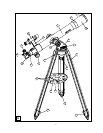
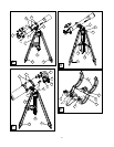
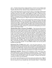
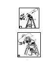
The telescope should now appear as in Fig. A, except that the viewfinder (A-4) has not yet
been attached.
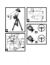
Note: Assembly of 60mm and 70mm models supplied with hardwood tripods is similar to the
assembly described above. Each tripod leg attaches with one of the supplied bolts (D-5)
through holes at the top of the leg; a washer and wing nut (D-6) fasten each leg to the base
of the yoke mount (D-7). The metal flange (D-1) of each wood tripod leg should face inward.
Attach the metal, triangle-shaped accessory shelf (D-2) to each of the three tripod legs using
the thumbscrews (D-3) and wing nuts provided. To adjust tripod height, slide the inner section
of each tripod leg up or down, securing it in position with firm-feel tightening (do not over-
tighten) of the thumbscrew (D-4).
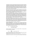
Assembly: 80mm, 90mm, 114mm, and 127mm Models — Place the tripod (with yoke mount
attached) on a flat surface and gently spread the three tripod legs outward until they are fully
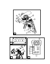
spread out. Each of these models includes a cradle ring system (B-1 or C-1), permitting the
optical tube to be moved upward or downward within the cradle rings for proper balancing of
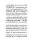
the tube on the yoke mount. As the yoke mount/tripod assembly is removed from the pack-
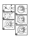
ing box, only the lower-half (E-1) of each cradle ring is present. Locate the upper half (E-4)
of each cradle ring in the packing box and connect each upper-half ring to its respective lower-
half ring by inserting the flange (E-2) of each upper-half ring into the slot (E-3) located at the
top of the lower-half ring. Be certain that each flange (E-2) is firmly seated into the corre-
sponding slot. Each upper-half ring should now close down to form a complete circular ring
without undue pressure being required. Open the upper-half rings and place the optical tube
into the cradle rings. See Fig. F. Close the rings and tighten (to a firm-feel only) the latches
(E-5). The telescope should now appear as in Figs. B or C, except that the viewfinder (B-6)
or (C-6) has not yet been attached. The flip-lock (B-9 or C-10) on each tripod leg permits
adjustment of tripod height.
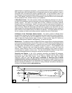
Balancing the Tube in the Mount (80mm, 90mm, 114mm, and 127mm models only): Loosen
slightly (by rotating half a turn counterclockwise) the vertical lock (B-2 or C-2). Placing your hand
on the upper end of the optical tube, move the tube up and down in a vertical direction within the
U-shape yoke mount (B-4 or C-4). The tube should move easily and be well-balanced about the
vertical axis of motion; if not, slightly loosen the cradle ring latches (E-5), move the optical tube
up-or-down within the cradle rings to achieve good balance, and re-tighten the latches (E-5).
Attaching the Viewfinder: Because the main telescope has a fairly narrow field of view,
locating objects directly in the main telescope can sometimes be difficult. The viewfinder (A-
4) is a small, wide-field telescope with crosshairs that permits easy object location. With the
viewfinder and main telescope aligned to each other, so that both point to the same position
in the sky, the observer first locates an object in the viewfinder; the object is then also posi-
tioned within the field of the main telescope.
The viewfinder bracket (A-5) attaches to the focuser housing at the position shown in Figs. A,
B, or C. (On 114mm and 127mm models the viewfinder bracket attaches to the mounting
block (C-7) located on the main telescope tube, near the focuser.) Using a “+” (Phillips-head)
- 7 -