


– 5 –
Looking at or near the Sun will cause irreversable damage to your eye. Do not point this telescope at or near the Sun. Do not look through the telescope as it is moving.
INTRODUCTION
Before you begin, we urge you to take a few minutes to completely read this manual so that you can
get the best use of the equipment.
This manual details the set-up, operation, specifications and
optional accessories of the Meade 90-AZ-ADR altazimuth refracting telescope. Designed for both
astronomical and terrestrial observing, the Meade 90-AZ-ADR will be your companion in exploring a
universe of celestial and earthly objects.
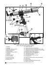
PARTS
• Complete optical tube assembly (objective lens diameter = 90mm; focal length = 900mm)
• Full-length, fully adjustable, aluminum tripod and accessory tray.
• MA25mm (36X), MA9mm eyepieces (100X), 1.25" O.D. “Outside Diameter”
• Diagonal mirror (1.25" O.D.)
• Red dot viewfinder
• Altazimuth mount
• Hardware package with bolts, wingnuts, nuts, etc. necessary for assembly
• Astronomy software (separate instructions supplied in software package) and instructional DVD
ASSEMBLY
You will need a Phillips-head screwdriver to assemble the tripod.
1. Remove and identify the telescope’s components, using the listing above.
2. Attach the 3 aluminum tripod legs (
7, Fig. 1) to the base of the altazimuth mount (25, Fig. 1) with
the 3 leg brace supports (8, Fig. 1) facing inward. Line up the holes of the tripod legs with the holes
on the mount base attachment (27, Fig. 1) and thread the three included bolts through the holes.
Thread the wing nuts over the bolts and hand-tighten to a firm feel. Stand the telescope upright
and spread the tripod legs evenly apart so that the accessory tray can be positioned for attachment
to the leg braces.
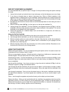
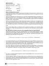
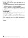
3. The tray helps stabilize the tripod and is also a convenient holder of eyepieces and other Meade
accessories, such as the Barlow lens. Line up the holes at the end of one of the leg brace supports
(9, Fig. 1) with the holes in one of the leg braces (8, Fig. 1). Thread one of the one-half inch bolts
through the holes. Thread a hex nut over the end of the bolt. Finger tighten the bolt and hex nut.
See Fig. 2. Repeat with the two other leg braces.
4. Thread the accessory tray (26, Fig. 1) over the center
mounting bolt and tighten to a firm feel.
5. Extend the sliding center portion of the adjustable
height tripod leg (19, Fig. 1) to the desired length for
all 3 legs. Lock the tripod legs by tightening the leg
lock thumbscrew (20, Fig. 1) to a firm feel. See Inset
A
.
6. If the cradle ring assembly (
5, Fig. 1) did not come attached to the optical tube (4, Fig. 1), loosen
the cradle ring lock knob (6,
Fig.
1
) and open the cradle rings. Place the optical tube roughly in the
center of the cradle rings and close the rings over the tube.
T
ighten the cradle ring lock knobs to
a firm feel. Do not overtighten—note that you may wish to change the position of the tube to gain
a more comfortable observing position of the eyepiece assembly.
7. Position the cradle ring’s mounting plate into the saddle plate slot (
18, Fig. 1). Tighten the mounting
lock knob (12, Fig. 1) to a firm feel.
8. Attach the red dot viewfinder bracket (24, Fig. 1) to the telescope using the 2 supplied
thumbscrews.
The thumbscrews thread over the 2 bolts located on the main tube.
11. Insert the diagonal mirror (13, Fig. 1) into the focuser drawtube (15, Fig. 1) and the MA 25mm
eyepiece (1, Fig. 1) into the diagonal mirror. Tighten the respective thumbscrews to a firm feel.
12. The telescope is now completely assembled. To move the telescope and point it from one object
another, first slightly loosen the vertical lock, then loosen the horizontal lock (
11, Fig. 1).
Loosening these locks allows the telescope to be moved freely (vertically or horizontally) in any
direction so that the telescope can be positioned to center a terrestrial or celestial object in the
telescopic field. Once an object is found, the vertical lock knob (
10, Fig. 1) can be tightened and
the vertical slow-motion fine-adjustment control knob (
16,
Fig.
1
) can then be used to make very
smooth and accurate tracking in the vertical axis.
Finger tighten the
hex nut
Fig. 2